

2 layers200 × 78.8 mm
Openridingcontroller rev2
Squalius-cephalus/OpenRidingController
D.I.Y horse riding controller for the PC.
30 parts13

A fleet of two autonomous guided vehicles (AGVs) that serve a self-built scale warehouse. Each vehicle runs on a custom ESP32 PCB and follows a taped line network.
Scheme is an open-source printed circuit board by marcel-gruszecki, from the marcel-gruszecki/Autonomous-AGV repository on GitHub, published under the MIT licence. It is a 2-layer board of 95.1 × 53.4 mm with 14 parts on 46 nets, routed with 530 tracks and 2 vias.
It is built around the TCRT5000. Its parts include 13 connectors and 1 switch.
A fleet of two autonomous guided vehicles (AGVs) that serve a self-built scale warehouse. Each vehicle runs on a custom ESP32 PCB and follows a taped line network. A Python control server plans collision-free routes for both robots, and a warehouse layer on top of it turns deliveries and customer orders into transport jobs.
The project covers the full development cycle: electrical schematic and PCB, hardware assembly, embedded firmware, multi-robot path planning, and warehouse logistics.
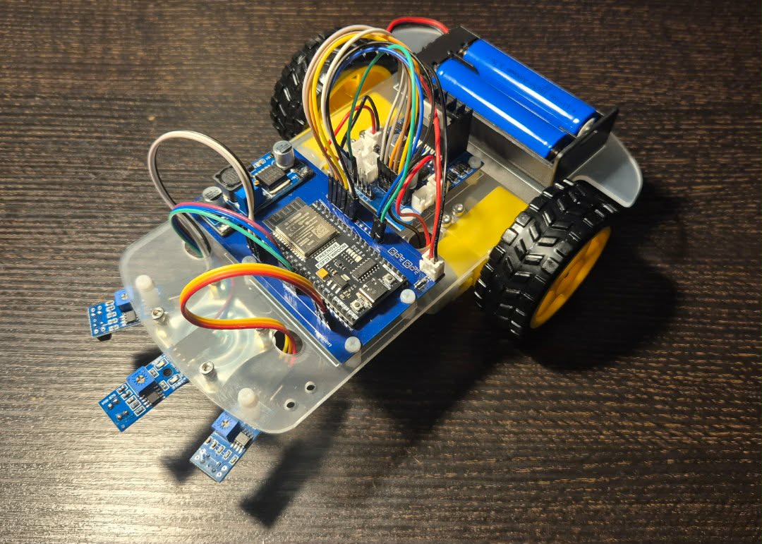
The mechanical platform comes from the OSOYOO 2WD Robot Car Starter Kit for Arduino, which was used as a chassis and drivetrain base only. The stock Arduino Uno and its motor shield were removed and replaced with a self-designed ESP32-WROOM carrier board, adding Wi-Fi connectivity and a 32-bit MCU in place of the original 8-bit controller.
https://github.com/user-attachments/assets/aa6393ad-4d51-4d18-ae9f-6a0b75ac840b
Custom PCB (KiCad, manufactured by PCBWay) — a single-board carrier designed from scratch, integrating:
Drivetrain and sensing — 2× DC gear motors driven through a Model-X dual H-bridge (PWM speed control on ENA/ENB), 3× TCRT5000 reflective sensors for line detection.
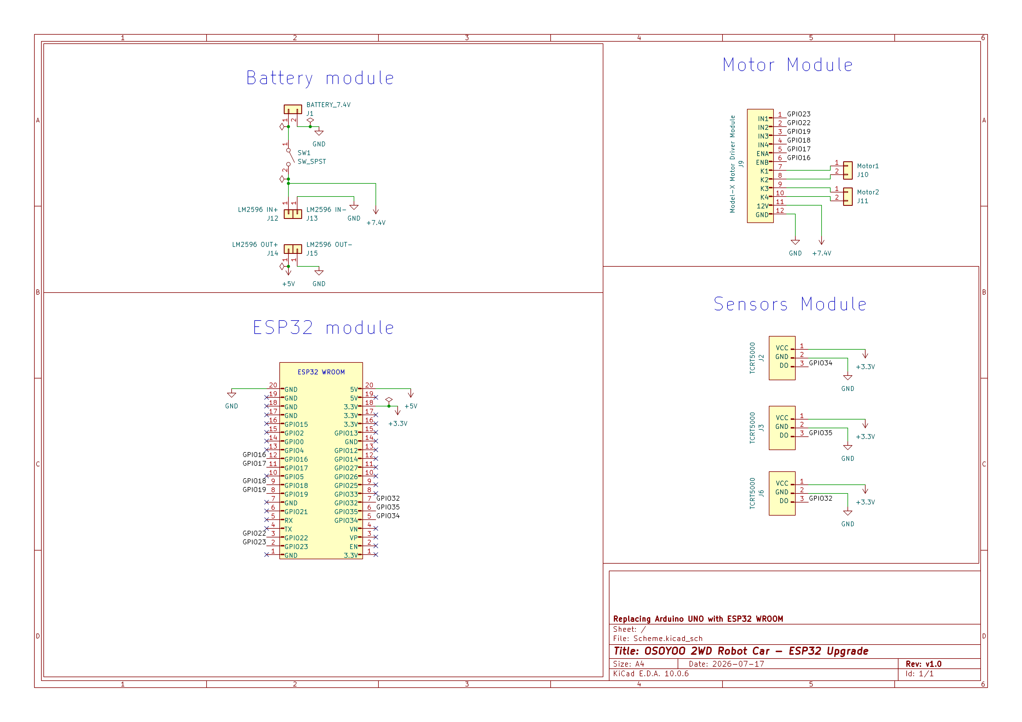
Electrical schematic: battery and power conversion, ESP32-WROOM module, motor driver interface, and the line-sensor array (KiCad).
The board was assembled by hand (T12 soldering station), including component selection, mechanical integration, and debugging of short-circuit and polarity faults on the first revision. Both robots use the same PCB revision.
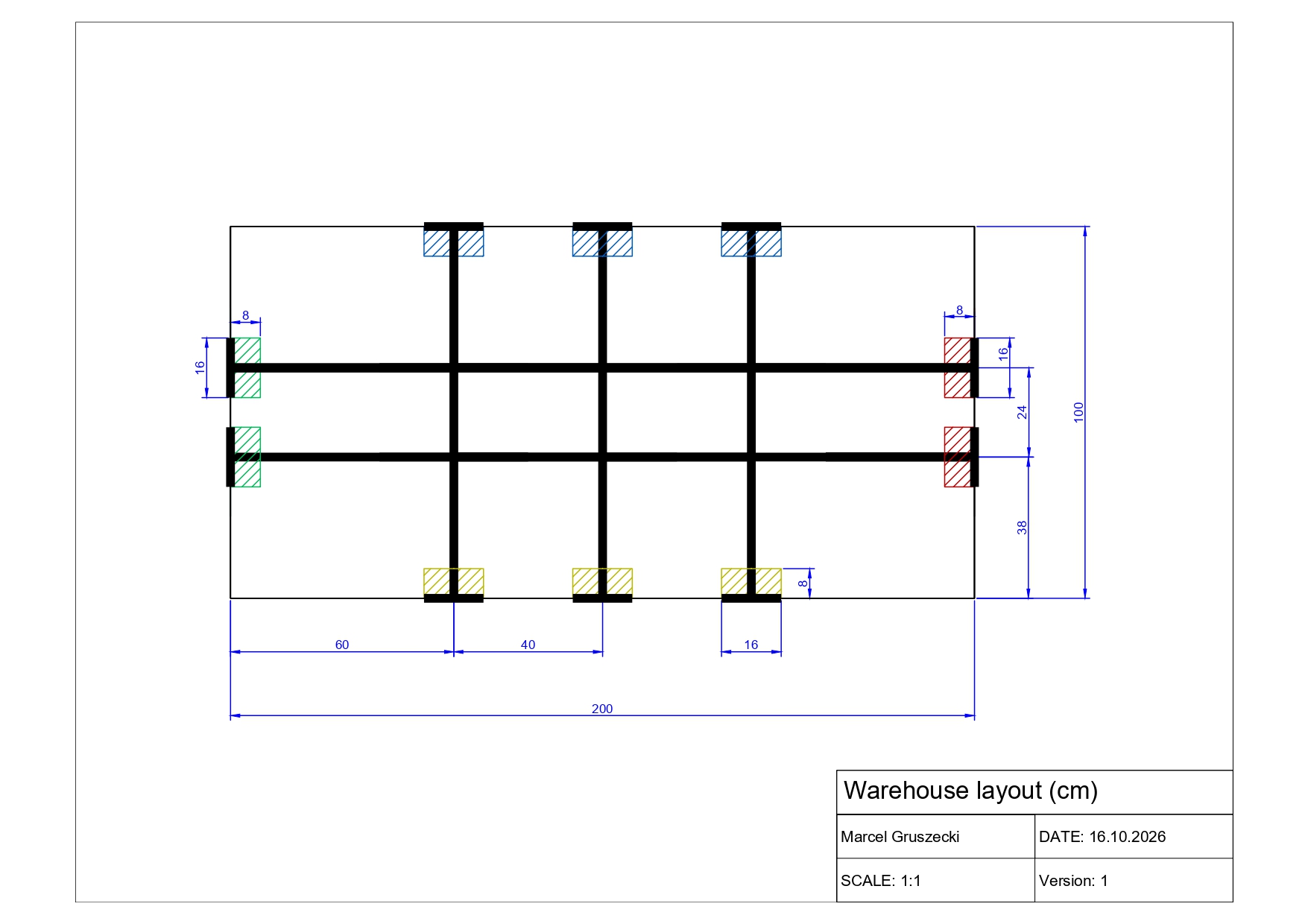
Scale 1:1, board 200 × 100 cm. CAD source: Warehouse_model/.
The track is a graph of 16 nodes, laid out with 3 cm wide tape. Coordinates are in cm, (0, 0) is the top-left corner, x grows to the right and y downwards.
| Node | Role | Position |
|---|---|---|
IN1, IN2 | Inbound stations — goods arrive here (green) | left edge, y = 38 / 62 |
OUT1, OUT2 | Outbound stations — goods leave here (red) | right edge, y = 38 / 62 |
C1, C2, C3 | Chargers / robot home positions (blue) | top edge, x = 60 / 100 / 140 |
R1, R2, R3 | Racks, one item type each: A→R1, B→R2, C→R3 (yellow) | bottom edge, x = 60 / 100 / 140 |
T60 … T140, B60 … B140 | Intersections of the two horizontal lines with the three vertical lines | y = 38 / 62 |
Stations, chargers and racks are fields — dead ends of a line with a stop bar.
A robot drives onto a field, stops on the bar, and turns 180° to leave. The two ends
of each short vertical connector (e.g. T60–B60) are treated as one place, so only
one robot can be on them at a time.
 warehouse.py  ──HTTP /goal, /status──▶  serwer.py  ◀──HTTP /command, /done──  ESP32 robot 1
 (stock, orders,                         (CBS path planning,                    ESP32 robot 2
  task dispatch)                          command scheduling)
OSOYOO/ — ESP32 firmware, C++ on the Arduino framework (PlatformIO). PD line
following on three sensors, turns at intersections, 180° turns on fields.Server/serwer.py — control server (Flask). Plans paths for all robots together
and hands each robot one command at a time.Server/mapf.py — multi-agent path finding: Conflict-Based Search
with space-time A*, turned into an Action Dependency Graph
so the robots stay collision-free even though they do not
move in lock-step.Server/warehouse.py — warehouse layer: keeps the rack stock, queues deliveries
and orders, and decides which robot goes where.Scheme/ — KiCad schematic, PCB layout, and Gerber files.Warehouse_model/ — CAD drawing of the warehouse board.The robot polls GET /command?robot=<id> every 100 ms and receives plain text
"<id> <COMMAND>" ("0 STOP" = nothing to do). After executing it, the robot confirms
with GET /done?robot=<id>&id=<id>. Until the confirmation arrives, the server keeps
returning the same command; the robot recognises the id it has already executed, so a
lost confirmation never makes it drive twice.
| Command | Meaning |
|---|---|
FORWARD [n] | Follow the line and stop on the stop bar of a field |
FORWARD_AFTER_LINE [n] | Follow the line and stop with the axle on an intersection; n = number of intersections to pass (straight drives are merged) |
TURN_LEFT, TURN_RIGHT | Rotate 90° on an intersection |
RETURN_LEFT, RETURN_RIGHT | Rotate 180° on a field, away from the neighbouring field |
STOP | Stand still |
| Endpoint | Used by | Description |
|---|---|---|
GET /command?robot=<id> | robot | Current command, see above |
GET /done?robot=<id>&id=<cmd id> | robot | Confirms a command, updates the robot position |
GET /goal?robot=<id>&to=<node> | warehouse | Sets a goal node and replans all robots; 400 {"error": ...} if the node is taken |
GET /status | warehouse | State of all robots, see JSON formats |
pip install -r Server/requirements.txt (Flask)cd OSOYOO/include
cp config.example.hpp config.hppEdit config.hpp:
const char* const WIFI_SSID  = "your-wifi";
const char* const WIFI_PASS  = "your-password";
const char* const SERVER_URL = "http://192.168.1.10:8080";   // IP of the PC running serwer.py

#define ROBOT_ID "1"   // "1" for the first robot, "3" for the second one
The robot ids must match the server: robot 1 starts on charger C1, robot 3 on
C3 (configured in robots in Server/serwer.py). config.hpp holds your Wi-Fi
password and is ignored by git.
Flash the robot (repeat for the second one with a different ROBOT_ID):
cd OSOYOO
pio run -t upload          # upload_port in platformio.ini: /dev/ttyUSB0
pio device monitor # optional: serial log, 115200 baudPut robot 1 on C1 and robot 3 on C3, facing the edge of the board (away from
the track). On the first start the server assumes exactly this position. After that
it remembers the positions in server_state.json; delete that file whenever you put
the robots back on their chargers by hand.
In two terminals, inside Server/:
python warehouse.py            # warehouse layer, interactive terminal
python serwer.py               # control server on port 8080
warehouse.py keeps retrying until the server answers, so the start order does not
matter. Once the robots connect to Wi-Fi they start polling for commands.
warehouse.py options:
python warehouse.py --simulate [--seed 42]                       # random deliveries and orders
python warehouse.py --replay logs/session_YYYYMMDD_HHMMSS.json   # repeat a recorded session
python warehouse.py --replay <file> --speed 2                    # ... twice as fast
serwer.py --random sends the robots to random free fields without the warehouse
(useful for testing the path planning alone).
>>> in A IN2       # item A arrived at IN2 -> a robot stores it on rack R1
>>> out A OUT1     # item A requested at OUT1 -> a robot takes it from R1 to OUT1
>>> status         # racks, waiting goods, waiting orders, robot tasks
>>> quit
Task priority: orders first (from the rack if it has stock, otherwise cross-docking straight from an inbound station if the item is waiting there), then storing waiting goods on racks that are not full (capacity 5). A robot with nothing to do returns to its charger.
All files are written atomically (to a .tmp file, then renamed), so a crash never
leaves a half-written file. Thanks to them both programs can be restarted at any time
and continue where they stopped.
Server/server_state.json — written by serwer.pySaved after every change of a robot's state.
{
  "next_id": 1761400000,
  "robots": {
    "1": {
      "position": "C1",
      "heading": "S",
      "goal": "R1",
      "actions": [
        {"cmd": "FORWARD", "to": "R1", "heading": "S", "seq": 4, "deps": [["3", 2]]}
      ],
      "current": {
        "id": 1761399999,
        "cmd": "FORWARD_AFTER_LINE 2",
        "actions": [
          {"cmd": "FORWARD", "to": "T60", "heading": "S", "seq": 2, "deps": []},
          {"cmd": "FORWARD", "to": "B60", "heading": "S", "seq": 3, "deps": []}
        ]
      },
      "done_seq": 1
    },
    "3": { "...": "same structure" }
  }
}| Field | Meaning |
|---|---|
next_id | Id of the next command. Starts at the Unix time, so ids keep growing across server restarts and a robot never mistakes a new command for an old one |
position, heading | Node the robot is on after its last confirmed command and the direction it faces (N, E, S, W; N = towards the chargers) |
goal | Node the robot should reach, null = stay |
actions | Planned actions not sent to the robot yet |
current | Command sent to the robot and waiting for /done, null if none. cmd is the text the robot receives, actions are the planned actions it covers |
done_seq | Sequence number of the robot's last finished action |
action cmd / to / heading | Planned move (FORWARD, TURN_LEFT, TURN_RIGHT, RETURN), the node and heading after it |
action seq | Sequence number of the action within its robot |
action deps | [robot, seq] pairs: the action may start only after that robot has finished action seq (i.e. has left the node this robot is about to enter) |
GET /status — returned by serwer.py, read by warehouse.py{
"1": {"position": "C1", "heading": "N", "home": "C1", "goal": "R1", "busy": true},
"3": {"position": "C3", "heading": "N", "home": "C3", "goal": null, "busy": false}
}home is the robot's charger. busy is true while the robot has a command in
progress, planned actions, or has not reached its goal yet.
Server/warehouse_state.json — written by warehouse.pySaved after every event and every pickup or drop.
{
  "racks": {"A": 2, "B": 0, "C": 5},
  "inbound": [{"item": "B", "station": "IN1"}],
  "orders": [{"item": "C", "station": "OUT2"}],
  "tasks": {
    "1": {"kind": "store", "item": "A", "pickup": "IN2", "drop": "R1", "stage": "drop"},
    "3": null
  }
}| Field | Meaning |
|---|---|
racks | Pieces on each rack, by item type (A → R1, B → R2, C → R3), max 5 |
inbound | Goods waiting at an inbound station, oldest first |
orders | Requests waiting at an outbound station, oldest first |
tasks | Task of each robot, null = idle |
task kind | store (IN → rack), deliver (rack → OUT) or crossdock (IN → OUT directly) |
task pickup, drop | Where the robot loads and unloads the item |
task stage | pickup = driving to the pickup node, drop = carrying the item to the drop node |
Server/logs/session_<date>_<time>.json — written by warehouse.pyEvery run (except --replay) records its events, so the same workload can be repeated
later with --replay.
{
  "initial_state": { "...": "warehouse_state.json at the start of the session" },
  "events": [
    {"t": 3.2, "type": "delivery", "item": "A", "station": "IN2"},
    {"t": 11.8, "type": "order", "item": "A", "station": "OUT1"}
  ]
}
t is the time in seconds since the start of the session, type is delivery
(goods arrived at an inbound station) or order (goods requested at an outbound
station).
KiCad · PCBWay · ESP32-WROOM · C++ / Arduino · PlatformIO · Python · Flask · Conflict-Based Search · Action Dependency Graph · HTTP
| Qty | Value | Footprint | References |
|---|---|---|---|
| 3 | TCRT5000 | Connector_PinSocket_2.54mm:PinSocket_1x03_P2.54mm_Vertical | J2, J3, J6 |
| 2 | Conn_01x20_Pin | Connector_PinSocket_2.54mm:PinSocket_1x20_P2.54mm_Vertical | J4, J5 |
| 1 | BATTERY_7.4V | Connector_PinHeader_2.54mm:PinHeader_1x02_P2.54mm_Vertical | J1 |
| 1 | LM2596 IN+ | TestPoint:TestPoint_Pad_3.0x3.0mm | J12 |
| 1 | LM2596 IN- | TestPoint:TestPoint_Pad_3.0x3.0mm | J13 |
| 1 | LM2596 OUT+ | TestPoint:TestPoint_Pad_3.0x3.0mm | J14 |
| 1 | LM2596 OUT- | TestPoint:TestPoint_Pad_3.0x3.0mm | J15 |
| 1 | Model-X Motor Driver Module | Connector_PinSocket_2.54mm:PinSocket_1x12_P2.54mm_Vertical | J9 |
| 1 | Motor1 | Connector_PinHeader_2.54mm:PinHeader_1x02_P2.54mm_Vertical | J10 |
| 1 | Motor2 | Connector_PinHeader_2.54mm:PinHeader_1x02_P2.54mm_Vertical | J11 |
| 1 | SW_SPST | Connector_PinSocket_2.54mm:PinSocket_1x02_P2.54mm_Vertical | SW1 |
Squalius-cephalus/OpenRidingController
D.I.Y horse riding controller for the PC.


xtarke/automated_buggy
This shield connects microcontroller (MSP-EXP430FR2355) pins to the car's power board. Go to Power Board for more hardware information.

Amrlxyz/esp-lfr-buggy
2nd Year Embedded Systems Project (ESP) - Line Following Robot Buggy


ciiiutnfrc/eduromaa
Versión educativa del robot móvil RoMAA (EduRoMAA)

billtsol/Maze
This project demonstrates how to use an Arduino board, IR sensors, and a motor driver shield to create a maze-solving robot.

Potato-eater/Legacy2026
github repo for Robocup Junior Australia lightweight soccer team
It measures 95.1 × 53.4 mm and has 2 copper layers, 1.6 mm thick.
14 parts, built around the TCRT5000. The full list of its parts is on this page, with links to each part's symbol and footprint where PCBKit's library has them.
From the marcel-gruszecki/Autonomous-AGV repository on GitHub, at the commit this page was made from: the board is Scheme/Scheme.kicad_pcb and its schematic Scheme/Scheme.kicad_sch. PCBKit opens the board in the browser, with nothing to install.
Its repository publishes it under the MIT licence: you may reuse it on that licence's terms (keep the author's notice, and for a copyleft licence share your changes alike).