2 layers85.6 × 26 mm
Game boy pico link board
agtbaskara/game-boy-pico-link-board
An Open-Source USB to Gameboy Link Cable Adapter for Raspberry Pi Pico
6 parts51MIT

 mAPBhlJ/PwmPump
Control modern (Grundfoss) heating water pumps via PWM
PwmPump is an open-source printed circuit board by mAPBhlJ, from the mAPBhlJ/PwmPump repository on GitHub, published under the AGPL-3.0 licence. It is a 2-layer board of 54 × 38 mm with 9 parts on 22 nets, routed with 26 tracks and 0 vias.
It is built around the BOB-12009. Its parts include 3 connectors and 2 ICs.
Modern heating (water)pumps can be controlled using PWM, this allows for fine-grained remote control regarding the pump speed, for integration into home automation software.
This project is designed to work work with the following pump(s):
Other (Grundfos) pumps may be compatible with little (software) changes, other brands may require hardware changes as well. Pull requests (even if it's just to update the list, are welcome)
Besides the pump, the project is built around the following hardware:
*The PCB is optional, you can build the same layout on a breadboard or perfboard. This project is created in LibrePCB but all files required for production are included.
The ESP32 is more capable as the ESP8266 but also has built-in WiFi, allowing more room for future functionalities. For safety and simpler schematics, 230V to 5V is done via a regular power adapter commonly used for phones.
The PCB is designed in KiCad, source files are available in the 'pcb/PwmPump' folder. If you do not want to change anything but just order the PCB's from any supplier, you can use the files in 'pcb/Fabrication'.
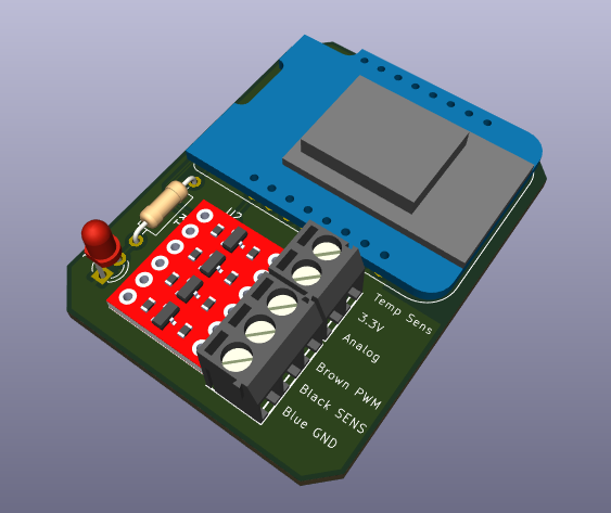
TODO:
Below there's some additional documentation used for troubleshooting/explanation, most is taken off the original Grundfoss manual (see sources below).
Using the 'Mini superseal' connector, make sure the connections are as following:
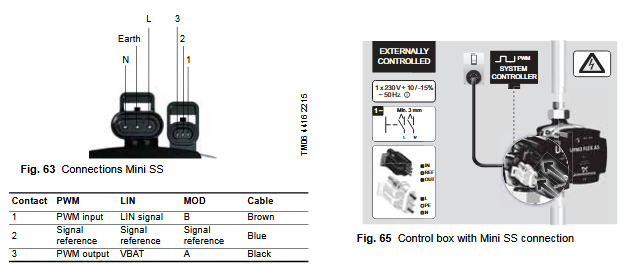
For PWM operation, the first LED should be red and the second LED should be yellow and LED 3/4/5 will show the current speed.
If the first/second LED are incorrect, refer to the steps below to change the mode of the UPM3.
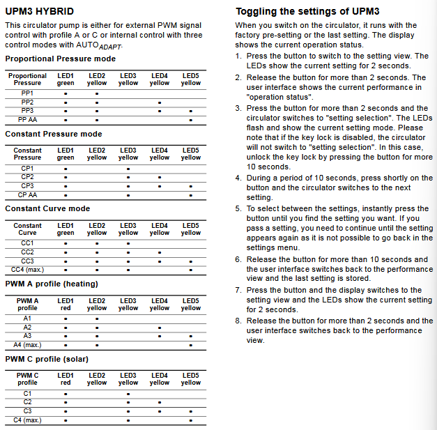
From the original Grundfoss PWM Documentation:
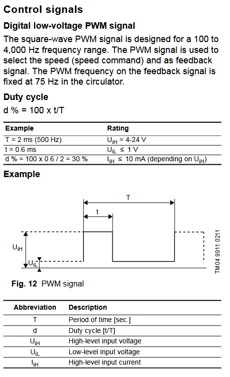
From the documentation we can conclude that the PWM signal of the ESP32 should have the following characteristics:
The feedback signal is 75 Hz (13 milliseconds)

If the signal is on for 95% of the time, the pump is off, anywhere within 0-70% is 0-70w or 0-140w consumption, any other percentage above 70% is an error situation, see table.
Original project start(s) in Dutch on Tweakers.net:
Project by a Russian with similar purpose (however using Arduino Nano with Bluetooth):
GNU Affero General Public License v3.0
Conditions ⓘ Disclose source ⓘ License and copyright notice ⓘ Network use is distribution ⓘ Same license ⓘ State changes
You should have received a copy of the GNU General Public License along with this program. If not, see https://www.gnu.org/licenses/.
| Qty | Value | Footprint | References |
|---|---|---|---|
| 3 | 3.5mm | PCM_SparkFun-Connector:ScrewTerminal_1x03_P3.5mm_Horizontal_Black | J1, J2, J3 |
| 1 | BOB-12009 | Libraries:CONV_BOB-12009 | U2 |
| 1 | LOGO | Libraries:tweakers_logo | G*** |
| 1 | WEMOS_C3_mini | RF_Module:WEMOS_C3_mini | U1 |
The 6 most common of 9 parts.
It measures 54 × 38 mm and has 2 copper layers, 1.6 mm thick.
9 parts, built around the BOB-12009. The full list of its parts is on this page, with links to each part's symbol and footprint where PCBKit's library has them.
From the mAPBhlJ/PwmPump repository on GitHub, at the commit this page was made from: the board is pcb/PwmPump/PwmPump.kicad_pcb and its schematic pcb/PwmPump/PwmPump.kicad_sch. PCBKit opens the board in the browser, with nothing to install.
Its repository publishes it under the AGPL-3.0 licence: you may reuse it on that licence's terms (keep the author's notice, and for a copyleft licence share your changes alike).
agtbaskara/game-boy-pico-link-board
An Open-Source USB to Gameboy Link Cable Adapter for Raspberry Pi Pico


VincentKobz/diy-weather-station
The goal is to build from scratch a small intelligent weather station that can be connected to IOT networks.


hselomein/Car-LED-Controller
This is a private repo for my car led project

JhouLab/Pi5WebcamRecorder
Records MV4 AVI video files from up to 4 simultaneous USB webcams on Raspberry Pi 5

michelkeijzers/fraxis
This project's personal goal is to learn more about ESP32 with ESP-IDF programming.