2 layers20.5 × 24.8 mm

 manthelt/Bitstream-Evolution-FilterBoard
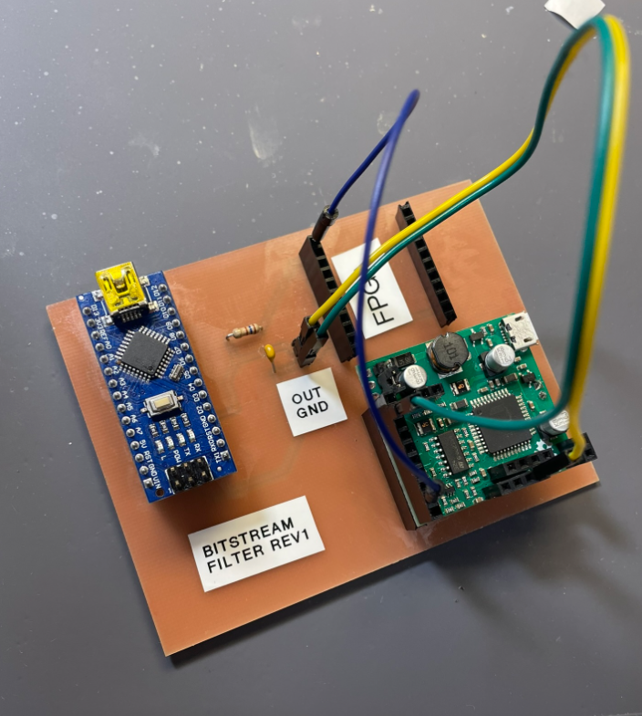
In short the signal generator was connected to the port where the FPGA signal is normally coming from and this is then connected to the ardunio nano through the PCB as normal.
Bitstream Evolution FilterBoard is an open-source printed circuit board by manthelt, from the manthelt/Bitstream-Evolution-FilterBoard repository on GitHub. It is a 2-layer board of 100.5 × 76 mm with 8 parts on 58 nets, routed with 24 tracks and 0 vias.
Its parts include 6 connectors, 1 capacitor and 1 resistor.
Logan Manthey Spring 2023-2024
Table of Contents
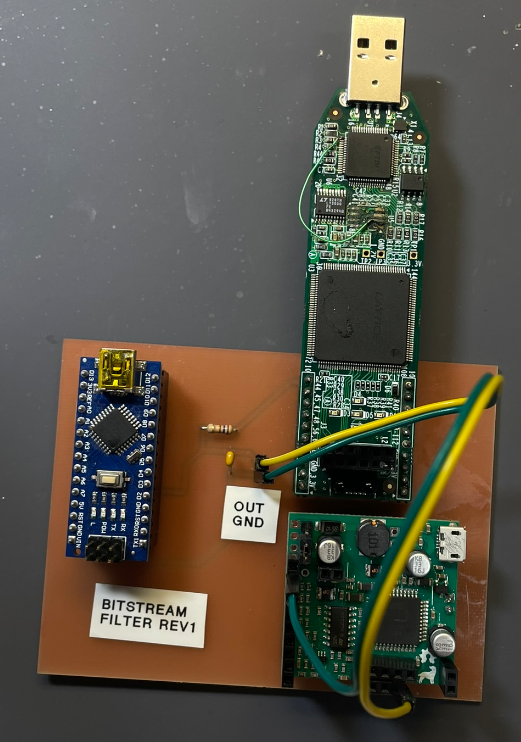
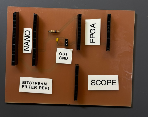
This board is a simple header board to be able to mount an FPGA, Ardunio Nano Microcontroller, and as ESPOtek Labador to it. This board also includes a basic passive low pass filter which will filter measurements on the ardunio to be more accurate to what we can accurately gather it will also ensure consistency with how we are gathering measurements as well. This PCB also allows us to test fit headers for future boards to build as well.
 |
|---|
| Populated PCB |
 |
|---|
| Unpopulated PCB |
 |
|---|
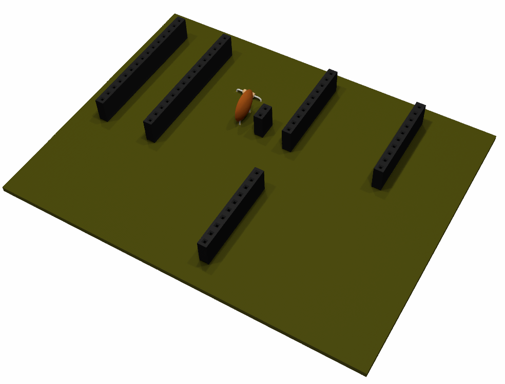
| PCB Render |
The following scope was used in this project. To find further documentation about both software and how to use the scope take a look at this link. EspoTek Link
Given this board has some filtering on it there needs to be some slight modification to the ReadSignal.ino file that has been used in the past. These modifications include filtering out values which are outside of the range of testing. To start I had this value just at 10K so basically filtering out any values below 10K which would include both values beyond what the nano can read and some that the nano can read. This will ensure that the only values sent back to the computer will be accurate values. Further testing to adjust this value may be required and will be updated in later revisions. See the below section [Testing the Filter](### Testing the Filter) for more infomation about finding this value.
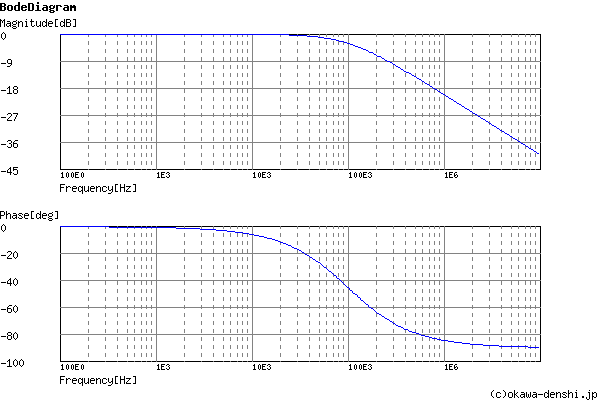
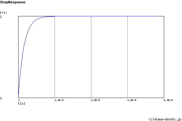
The filter used has a 160 ohm resistor and a 0.01 uF capacitor this gives a -3dB cutoff frequency of 99471.8394 Hz. In testing at 3.3 volts this will give us an accurate interrupt reading range on the ardunio of between 10kHz and 60Khz with only some aliasing around the 55kHz to 60Khz range. This is much better than not using as there will be aliasing anywhere above about 100kHz whereas this will simply just filter those values out. Though this is an extremly simple filter it will allow us to ensure that our measurements we are getting are in a certain measureable range while still maintaining affordability. During some initial testing of this I found that the max value we could accurately measure with the interrupt counter was at about 60Khz.
 |
|---|
| Bode Plot |
 |
|---|
| Step Response |
To test the filter the following configuration on the board was used.
 |
|---|
| Filter Testing Setup |
In short the signal generator was connected to the port where the FPGA signal is normally coming from and this is then connected to the ardunio nano through the PCB as normal. The scope section was connected as normal as well to monitor the filter.
| Part | Quanity |
|---|---|
| 160 Ohm Resistor | 1 |
| 0.01 uF Capacitor | 1 |
| 10 Pin 2.54mm Female Header | 3 |
| 15 Pin 2.54 Female Header | 2 |
Due to measuring with a ruler the pin placement is less than ideal. Getting better measurements using a caliper instead should fix this in the next revision.
I wasn't quite a fan of how the through hole parts fit with the footprints that I had. This isn't a huge issue but may want to fix for the next revision of this board.
This board is a part of a series of more iterative and rapid prototyping boards rather than a complete all encompassing board. This is the first in that series which is meant to test the specifics of the pulse count experiment.
| Qty | Value | Footprint | References |
|---|---|---|---|
| 3 | Conn_01x10_Female | Connector_PinSocket_2.54mm:PinSocket_1x10_P2.54mm_Vertical | J3, J4, J6 |
| 2 | Conn_01x15_Female | Connector_PinSocket_2.54mm:PinSocket_1x15_P2.54mm_Vertical | J1, J2 |
| 1 | 0.01u | Capacitor_THT:C_Disc_D9.0mm_W2.5mm_P5.00mm | C1 |
| 1 | 160 | Resistor_THT:R_Axial_DIN0204_L3.6mm_D1.6mm_P7.62mm_Horizontal | R1 |
| 1 | Conn_01x02_Male | Connector_PinSocket_2.54mm:PinSocket_1x02_P2.54mm_Vertical | J5 |
It measures 100.5 × 76 mm and has 2 copper layers, 1.6 mm thick.
8 parts. The full list of its parts is on this page, with links to each part's symbol and footprint where PCBKit's library has them.
From the manthelt/Bitstream-Evolution-FilterBoard repository on GitHub, at the commit this page was made from: the board is Bitstream_Evolution_Filterboard/Bitstream_Evolution_Filterboard.kicad_pcb and its schematic Bitstream_Evolution_Filterboard/Bitstream_Evolution_Filterboard.kicad_sch. PCBKit opens the board in the browser, with nothing to install.
Its repository states no licence, so its author keeps all rights: ask manthelt before reusing the design.

joeycastillo/Sensor-Watch
A board replacement for the classic Casio F-91W wristwatch

rusefi/rusefi
rusefi - GPL internal combustion engine control unit

hoglet67/RGBtoHDMI
Bare-metal Raspberry Pi project that provides pixel-perfect sampling of Retro Computer RGB/YUV video and conversion to HDMI

shanteacontrols/OpenDeck
A platform for building interactive control and sensing devices using MIDI and OSC built with Zephyr RTOS.

hackclub/OnBoard
💡 Join 1,000 teenagers and make your first PCB with a $100 grant!

dangiu/PicoMemcard
Emulating PSX Memory Card (or controller) using a Raspberry Pi Pico

OLIMEX/DIY-LAPTOP
Do It Yourself Open Source Hardware and Software Modular Hacker's Friendly Laptop