6 layers139.7 × 88.9 mm

 maltaisn/game-console5
Small handheld game console with 6 buttons, 1.5" grayscale display, with bootloader and multi-games support.
Console is an open-source printed circuit board by maltaisn, from the maltaisn/game-console repository on GitHub, published under the Apache-2.0 licence. It is a 4-layer board of 45 × 65 mm with 84 parts on 56 nets, routed with 561 tracks and 166 vias.
It is built around the ATMEGA3208-MU, AP3401KTTR-G1 and AT25SF081B-SSHB-T, with the MIC2250-2YD5-TR, MCP73831-2ATI/OT and AP2301 among its other parts. Its parts include 26 resistors, 17 capacitors, 7 diodes, 7 transistors and 7 switches. It belongs with the AVR (ATmega, ATtiny) boards of this library.


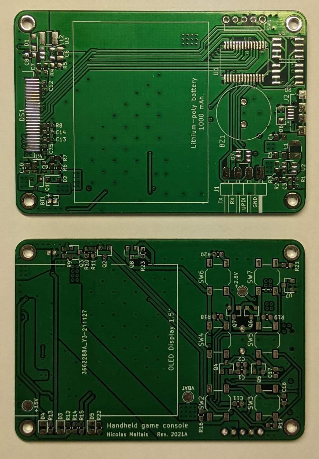
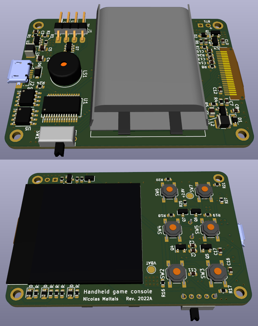
The PCB was designed in KiCAD 6. Two revisions were made, but only the first revision was manufactured since it was already working with minor changes.
Other notable changes that should be made:
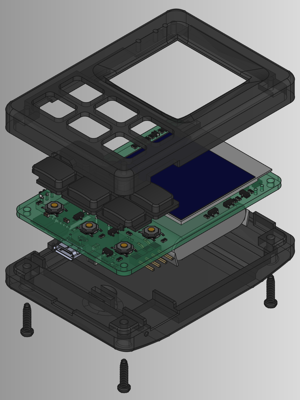
The enclosure was designed in FreeCAD and 3D printed in black MJF Nylon. The design is fine considering this was my first experience with 3D modeling and considering that it wasn't planned for carefully at the time of designing the PCB. The button design could have been better, they sometimes get stuck and don't click, but this is usually not an issue.
| Qty | Value | Footprint | References |
|---|---|---|---|
| 7 | 10k | Resistor_SMD:R_0603_1608Metric | R6, R16, R17, R18, R19, R20, R21 |
| 6 | 100k | Resistor_SMD:R_0603_1608Metric | R3, R9, R24, R25, R26, R27 |
| 6 | SW_Push | Button_Switch_SMD:SW_SPST_TL3342 | SW2, SW3, SW4, SW5, SW6, SW7 |
| 4 | 0.1uF | Capacitor_SMD:C_0603_1608Metric | C2, C11, C16, C17 |
| 4 | AP2301 | Package_TO_SOT_SMD:SOT-23 | Q1, Q3, Q4, Q6 |
| 4 | MH | MountingHole:MountingHole_2.2mm_M2_ISO7380_Pad | H1, H2, H3, H4 |
| 3 | 10uF | Capacitor_SMD:C_0805_2012Metric | C4, C5, C6 |
| 3 | 4.7uF | Capacitor_SMD:C_0603_1608Metric | C9, C10, C15 |
| 3 | AP2302 | Package_TO_SOT_SMD:SOT-23 | Q2, Q5, Q7 |
| 2 | 1uF | Capacitor_SMD:C_0603_1608Metric | C13, C14 |
| 2 | CUS520 | Diode_SMD:D_SOD-323_HandSoldering | D1, D2 |
| 1 | +15V | TestPoint:TestPoint_Pad_D2.0mm | TP1 |
| 1 | +2.8V | TestPoint:TestPoint_Pad_D2.0mm | TP2 |
| 1 | 1.2M | Resistor_SMD:R_0603_1608Metric | R8 |
| 1 | 1.2k | Resistor_SMD:R_0603_1608Metric | R12 |
| 1 | 10nF | Capacitor_SMD:C_0603_1608Metric | C1 |
| 1 | 10uH | Inductor_SMD:L_1210_3225Metric | L2 |
| 1 | 12k | Resistor_SMD:R_0603_1608Metric | R13 |
| 1 | 18k | Resistor_SMD:R_0603_1608Metric | R10 |
| 1 | 2.2uF/25V | Capacitor_SMD:C_0603_1608Metric | C8 |
| 1 | 2.2uH | Inductor_SMD:L_1210_3225Metric | L1 |
| 1 | 20k | Resistor_SMD:R_0603_1608Metric | R14 |
| 1 | 22k | Resistor_SMD:R_0603_1608Metric | R11 |
| 1 | 22pF | Capacitor_SMD:C_0603_1608Metric | C3 |
| 1 | 27k | Resistor_SMD:R_0603_1608Metric | R15 |
| 1 | 3.9k | Resistor_SMD:R_0603_1608Metric | R7 |
| 1 | 330k | Resistor_SMD:R_0603_1608Metric | R1 |
| 1 | 4.7uF/25V | Capacitor_SMD:C_0603_1608Metric | C12 |
| 1 | 470R | Resistor_SMD:R_0603_1608Metric | R22 |
| 1 | 470pF | Capacitor_SMD:C_0603_1608Metric | C7 |
| 1 | 804030 | console:Battery-804030 | BT1 |
| 1 | 82k | Resistor_SMD:R_0603_1608Metric | R5 |
| 1 | 910k | Resistor_SMD:R_0603_1608Metric | R4 |
| 1 | 91k | Resistor_SMD:R_0603_1608Metric | R2 |
| 1 | AP3401KTTR | Package_TO_SOT_SMD:SOT-23-6 | U2 |
| 1 | AT25SF081B-SSHB-T | Package_SO:SOIC-8_3.9x4.9mm_P1.27mm | U5 |
| 1 | ATmega3208 | Package_SO:SSOP-28_5.3x10.2mm_P0.65mm | U1 |
| 1 | Charging | Diode_SMD:D_0805_2012Metric | D3 |
| 1 | Complete | Diode_SMD:D_0805_2012Metric | D4 |
| 1 | D5V0P4URL6SO | Package_TO_SOT_SMD:SOT-23-6 | D7 |
| 1 | Debug Port | console:Debug_Port | J1 |
| 1 | ER-OLED015-3 | console:ER-OLED015-3 | DS1 |
| 1 | FT25C32A | Package_SO:SO-8_3.9x4.9mm_P1.27mm | U6 |
| 1 | LED | Diode_SMD:D_0805_2012Metric | D5 |
| 1 | MCP73831-2ATI | Package_TO_SOT_SMD:SOT-23-5 | U4 |
| 1 | MIC2250-2YD5-TR | Package_TO_SOT_SMD:SOT-23-5 | U3 |
| 1 | ON/OFF | console:1825232-1 | SW1 |
| 1 | SMF6.0CA | Diode_SMD:D_SOD-123F | D6 |
| 1 | Speaker | console:Speaker | LS1 |
| 1 | USB B Micro | console:CUI_UJ2-MIBH-G-SMT-TR | J2 |
| 1 | VBAT | TestPoint:TestPoint_Pad_D2.0mm | TP3 |
It measures 45 × 65 mm and has 4 copper layers, 1.6 mm thick.
84 parts, built around the ATMEGA3208-MU, AP3401KTTR-G1, AT25SF081B-SSHB-T and MIC2250-2YD5-TR. The full list of its parts is on this page, with links to each part's symbol and footprint where PCBKit's library has them.
From the maltaisn/game-console repository on GitHub, at the commit this page was made from: the board is hw/console.kicad_pcb and its schematic hw/console.kicad_sch. PCBKit opens the board in the browser, with nothing to install.
Its repository publishes it under the Apache-2.0 licence: you may reuse it on that licence's terms (keep the author's notice, and for a copyleft licence share your changes alike).


eauel/openzmeter
openzmeter (oZm) is an Open Source system designed for power quality analysis and smart energy metering in power networks. It has been designed to comply with international standards IEC 61000-4-30 and EN 50160.

perpuchaty/MQTT-Geiger-Counter
Portable Geiger counter with WiFi and MQTT. Home assistant compatible

R-Mutura/DISHWASHER
Contains hardware and Software implementation of a dishwasher product


anthony-bernaert/ftdi-jtag-programmer
FTDI-based JTAG Programmer Circuit for FPGAs

SimosMCmuffin/FlexiBMS_hardware
Open Source BMS developed by Simo Sihvonen (Simos MCmuffin) with the Esk8 community, for the Esk8 community