
4 layers70.8 × 108 mm
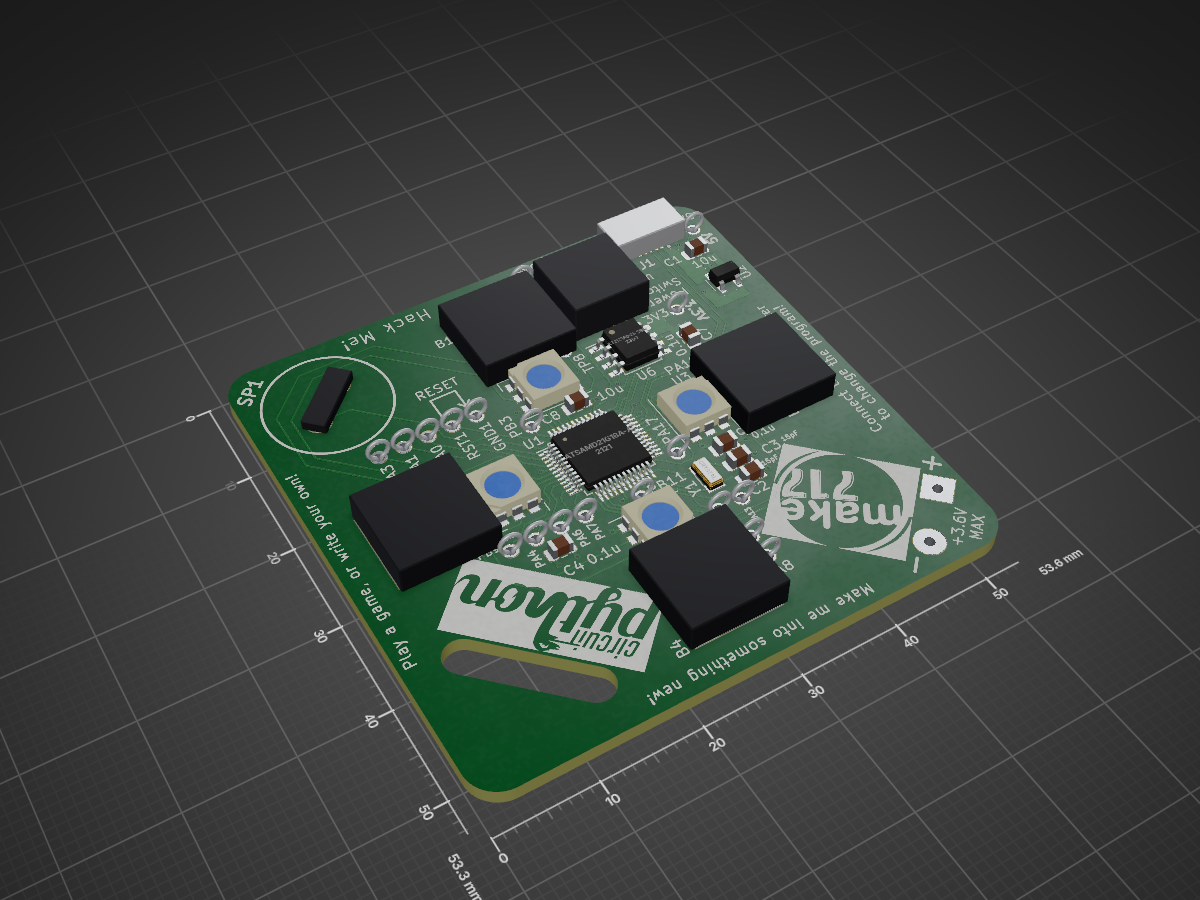
KiCad PCB files for custom Make717 memory game soldering badge
Badge is an open-source printed circuit board by make717, from the make717/MemoryGame-PCB repository on GitHub. It is a 2-layer board of 53.6 × 53.3 mm with 53 parts on 59 nets, routed with 467 tracks and 39 vias.
It is built around the SK9822, MIC5504-3.3YM5 and 10118193-0001LF, with the JS202011SCQN and PKM13EPYH4000-A0 among its other parts. Its parts include 8 capacitors, 7 ICs, 1 connector, 1 switch and 1 crystal. It belongs with the lEDs and displays boards and the SAM D and SAM boards of this library.


KiCad PCB files for custom Make717 memory game soldering badge. This badge was designed and built by members of Make717 for a soldering event at the Lancaster Science Factory on April 27, 2019.
This badge is using the SAMD21G 32-bit microcontroller running CircuitPython. Thank you to Adafruit.

The badge is powered by either USB or two AAA batteries (SW1 "Power Switch" can be either in USB or BATT). If using batteries, ensure they are 1.5 volts and fully charged. The badge might not power up with recharable batteries which are often rated at 1.2 volts. The USB connection goes through a voltage regulator to supply 3.3 volts to the microcontroller and other components on the board.
If you are joining us at Make717, or have all the component to build a badge, you can follow the assembling instructions which include tips on what to check if the badge is not working.
You can update the firmware on the badge over USB by droping an updated UF2 image when in bootloader mode. To enter this mode, double tap the RST1 to GND1 while powered over USB. The drive should reappear as MAKEBOOT when it has entered this mode.
It is also possible to directly program the SAMD21G18A using Serial Wire Debug (SWD). We recommend a J-LINK programmer or similar, connecting to SWDIO1 (data), SWCLK1 (clock), GND1 (ground), and 3V3 (power). You will also need to power the board with 3.3 volts which can be done via the USB connection while programming or the 5V pin near the USB port.
| Qty | Value | Footprint | References |
|---|---|---|---|
| 24 | TestPoint | TestPoint:TestPoint_THTPad_D1.5mm_Drill1.0mm | 3V3, 5V0, GND1, PA0, PA1, PA3, PA4, PA6, PA7, PA8, PA9, PA12, PA13, PA17, PA18, PA19 +8 |
| 4 | PTC_pad_badge | PCB_proj:PTC_badge | B1, B2, B3, B4 |
| 4 | SK9822 | LED_SMD:LED_WS2812_PLCC6_5.0x5.0mm_P1.6mm | U3, U4, U5, U7 |
| 3 | 0.1u | Capacitor_SMD:C_0805_2012Metric | C4, C5, C7 |
| 3 | 10u | Capacitor_SMD:C_0805_2012Metric | C1, C6, C8 |
| 2 | 15pF | Capacitor_SMD:C_0805_2012Metric | C2, C3 |
| 1 | 10118193-0001LF | usb:usb | J1 |
| 1 | AAA_holder | PCB_proj:aaa_battery_holder | BH1 |
| 1 | AT25SF041-SSHD-B | Package_SO:SOIC-8_3.9x4.9mm_P1.27mm | U6 |
| 1 | ATSAMD21G18A-AUT | Package_QFP:TQFP-48_7x7mm_P0.5mm | U1 |
| 1 | Crystal | Crystal:Crystal_SMD_3215-2Pin_3.2x1.5mm | Y1 |
| 1 | JS202011SCQN | PCB_proj:JS202011SCQN | SW1 |
| 1 | LOGO | PCB_proj:LOGO | G*** |
| 1 | MIC5504-3.3YM5 | Package_TO_SOT_SMD:SOT-23-5 | U2 |
| 1 | PKM13EPYH4000-A0 | PCB_proj:PKM13EPYH4002-B0 | SP1 |
| 1 | blink_small | PCB_proj:blink_small | G*** |
| 1 | cp_logo | PCB_proj:cp_logo | G*** |
| 1 | make_717_logo_small | PCB_proj:make_717_logo_small | G*** |
The 52 most common of 53 parts.
It measures 53.6 × 53.3 mm and has 2 copper layers, 1.6 mm thick.
53 parts, built around the SK9822, MIC5504-3.3YM5, 10118193-0001LF and JS202011SCQN. The full list of its parts is on this page, with links to each part's symbol and footprint where PCBKit's library has them.
From the make717/MemoryGame-PCB repository on GitHub, at the commit this page was made from: the board is pcb_files/badge.kicad_pcb. PCBKit opens the board in the browser, with nothing to install.
Its repository states no licence, so its author keeps all rights: ask make717 before reusing the design.

ducman1998/basket-ball-robot
DeltaX Basketball Track robot (University of Tartu) | Source code, robot design and electronic schematics |🥉Won 3rd place out of 10 teams | The fastest robot in the competition

andremdaraujo/EMBARCADOS-CURSO-PCB
Projeto desenvolvido durante o curso Projeto de PCB para Sistemas Embarcados

Acliad/toast-o-meter
Breadboard mounted DMM with volts, amps, ohms, continuity, and diode feature.

fgervais/project-nrf-leak-detector_hardware
Install it and forget it: Detect leaks for over 20 years on a coin cell.

r3dpath/RpiFly_Hardware
While most of the functionality here has been tested to work theres certainally some marginal design decisions, just beware.

AnaviTechnology/anavi-noisy
Raspberry Pi add-on with a buzzer, a LED and a button. Designed as a simple soldering kit.

syamei0/kicad
仕様 ・圧電スピーカーは0ピン ・CANはTXDが5ピン、RXDが4ピン ・JP3とJP4はcanの終端抵抗 ・上バー付の数字はPWM可 ・白抜き文字は書き込み中プルアップ