2 layers87.5 × 103 mm
CAN Cybersecurity Hardware
naveesh1/CAN-Cybersecurity-Project
Real-Time Embedded Cybersecurity and Anomalous Message Detection for In-Vehicle CAN Networks
12 parts

 Majr98/pelletmon1
Monitor Estyma-compatibile boiler via CANbus with WiFi / IoT.
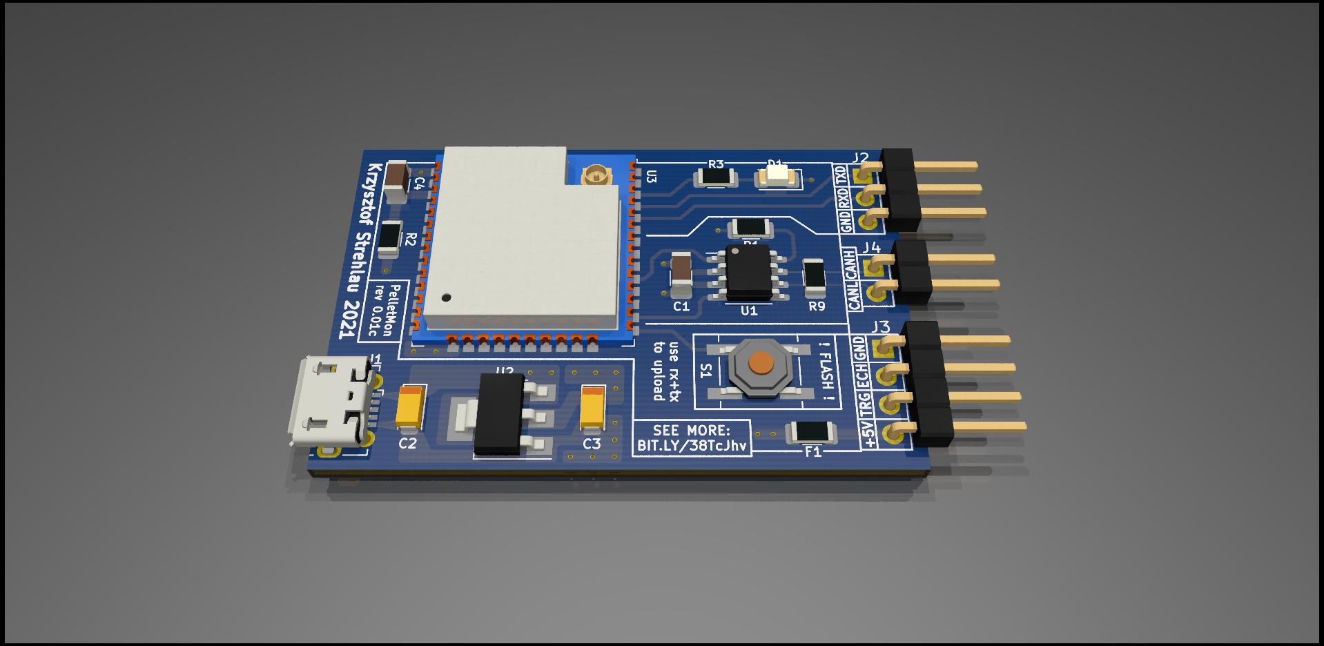
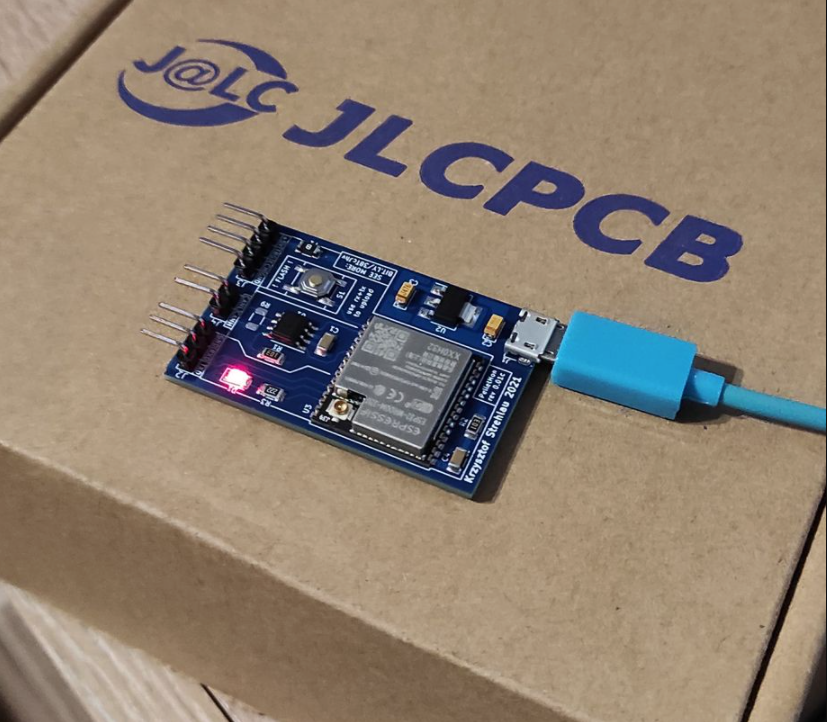
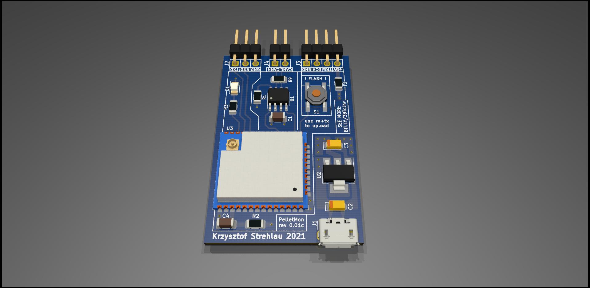
Pelletmon is an open-source printed circuit board by Majr98, from the Majr98/pelletmon repository on GitHub, published under the GPL-3.0 licence. It is a 4-layer board of 48 × 31.4 mm with 18 parts on 18 nets, routed with 112 tracks and 40 vias.
It is built around the ESP32-WROOM-32, SN65HVD230D and AMS1117-3.3. Its parts include 4 capacitors, 4 resistors, 4 connectors, 3 ICs and 1 diode. It belongs with the radio and wireless and interfaces and adapters boards and the ESP32 boards of this library.


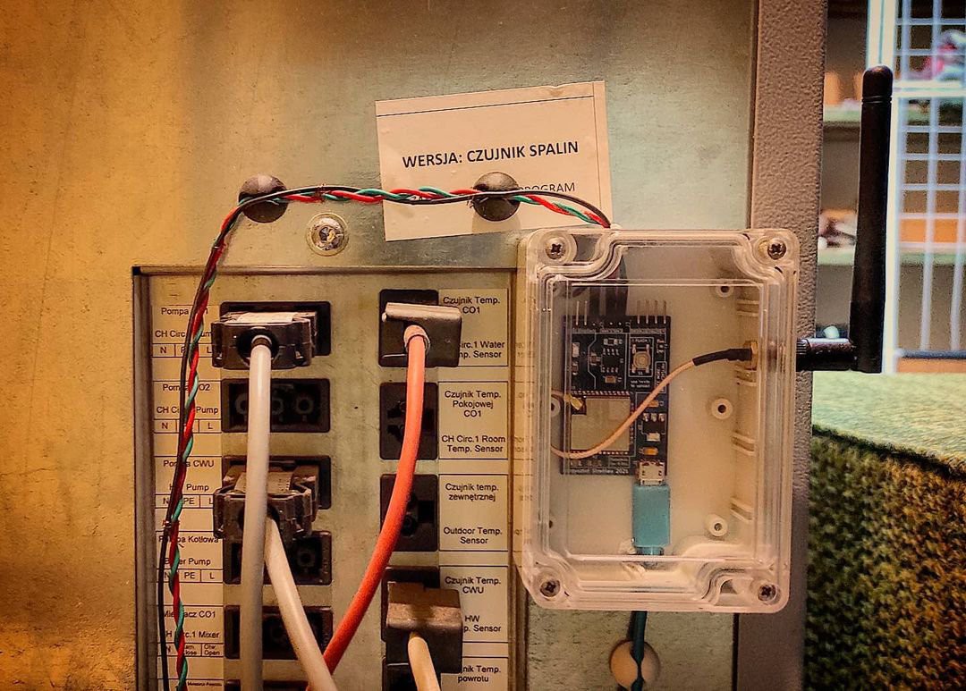
Our old boiler was previously connected to my IoT system. After replacing the boiler with a new one, we no longer have this option. So why not introduce it to a new boiler?
The goal of the project is to reverse engineer the CAN communication of the new boiler and expose real-time data to the IoT. By the way, the HC-SR04 sensor will measure the fuel level in the tank.
The project will have its own PCB. Communication with the outside world will be carried out using ESP32 and fuel level measurement using HC-SR04. The SN65HVD230 chip will be used as the CAN transceiver. The software will be written in the Arduino environment in C ++ and will be powered with my IoT framework - ksIotFrameworkLib.
| Qty | Value | Footprint | References |
|---|---|---|---|
| 2 | 0.1uF | Capacitor_SMD:C_1206_3216Metric | C1, C4 |
| 2 | 10k | Resistor_SMD:R_1206_3216Metric | R1, R2 |
| 1 | 10µf | Capacitor_Tantalum_SMD:CP_EIA-3216-10_Kemet-I | C2 |
| 1 | 120R | Resistor_SMD:R_1206_3216Metric | R9 |
| 1 | 220R | Resistor_SMD:R_1206_3216Metric | R3 |
| 1 | 47µf | Capacitor_Tantalum_SMD:CP_EIA-3216-10_Kemet-I | C3 |
| 1 | AMS1117-3.3 | Package_TO_SOT_SMD:SOT-223-3_TabPin2 | U2 |
| 1 | CFG | LED_SMD:LED_1206_3216Metric | D1 |
| 1 | Conn_01x02 | Connector_PinHeader_2.54mm:PinHeader_1x02_P2.54mm_Vertical | J4 |
| 1 | Conn_01x03 | Connector_PinHeader_2.54mm:PinHeader_1x03_P2.54mm_Vertical | J2 |
| 1 | Conn_01x04 | Connector_PinHeader_2.54mm:PinHeader_1x04_P2.54mm_Vertical | J3 |
| 1 | ESP32-WROOM-32 | RF_Module:ESP32-WROOM-32U | U3 |
| 1 | Polyfuse_Small | Resistor_SMD:R_1206_3216Metric | F1 |
| 1 | SN65HVD230 | Package_SO:SOIC-8_3.9x4.9mm_P1.27mm | U1 |
| 1 | SW_Push | Button_Switch_SMD:SW_SPST_B3SL-1022P | S1 |
| 1 | USB_B_Micro | Connector_USB:USB_Micro-B_Molex-105017-0001 | J1 |
It measures 48 × 31.4 mm and has 4 copper layers, 1.6 mm thick.
18 parts, built around the ESP32-WROOM-32, SN65HVD230D and AMS1117-3.3. The full list of its parts is on this page, with links to each part's symbol and footprint where PCBKit's library has them.
From the Majr98/pelletmon repository on GitHub, at the commit this page was made from: the board is hardware/PelletMon.kicad_pcb. PCBKit opens the board in the browser, with nothing to install.
Its repository publishes it under the GPL-3.0 licence: you may reuse it on that licence's terms (keep the author's notice, and for a copyleft licence share your changes alike).
naveesh1/CAN-Cybersecurity-Project
Real-Time Embedded Cybersecurity and Anomalous Message Detection for In-Vehicle CAN Networks

nsm81/VehiclePrecharge_PCB
The precharge board contains the precharge resistors, precharge relay, main relay drivers (with economisers), and a controlling micro.


vyrubaev/TV-Lift-Controller
TVLift Controller is an intelligent controller for TV lift and lower mechanisms, based on the ESP32 microcontroller.

nsm81/VehicleJunctionBox_PCBs
The junction box is an intermediate stage between the accumulator and inverter. It contains an HVD, a current sensor, discharge circuitry, TSAL and TSMPs.

nsm81/VehicleVCU_PCB
A Vehicle Control Unit provides multiple CANBUS transceivers for communication within a vehicle.

ampnics/CAN-to-WiFi-Converter-Dongle-
CAN to WiFi Converter PCB using ESP32! This step-by-step tutorial covers schematic creation, PCB layout, and best practices for signal integrity. Perfect for automotive and IoT applications!

blinken/vandal
An ESP32-based lighting control system for campervans (or anything else)