2 layers22.9 × 48.5 mm
Breakout for attiny88 V1
mail4johnv/ATTiny88_Breakout_Board
Kicad files for attiny88_Breakout_board.
12 partsMPL-2.0

 mail4johnv/ATTiny88_Breakout_Board
Kicad files for attiny88_Breakout_board.
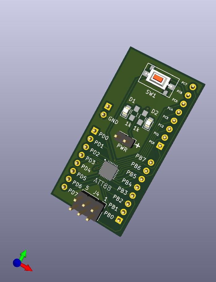
Breakout for attiny88 is an open-source printed circuit board by mail4johnv, from the mail4johnv/ATTiny88_Breakout_Board repository on GitHub, published under the MPL-2.0 licence. It is a 2-layer board of 23.2 × 47.5 mm with 14 parts on 28 nets, routed with 224 tracks and 9 vias.
Its parts include 6 connectors, 3 resistors, 2 diodes, 1 capacitor and 1 IC. It belongs with the interfaces and adapters and microcontroller boards boards and the AVR (ATmega, ATtiny) boards of this library.
A compact breakout board for the Microchip/Atmel ATtiny88 microcontroller. This repository contains the KiCad source, PCB/gerber exports, BOM, assembly notes, and example firmware to help you build and use the board.
Status
Quick links
Features
Repository layout
Quick start (build & test)
License This project is released under the Mozilla Public License 2.0 — see LICENSE for full text.
Maintainer
| Qty | Value | Footprint | References |
|---|---|---|---|
| 3 | Conn_01x08 | Connector_PinHeader_2.54mm:PinHeader_1x08_P2.54mm_Vertical | J1, J2, J3 |
| 2 | 1k | Resistors_SMD:R_0805_HandSoldering | R2, R3 |
| 2 | Conn_01x02 | Connector_PinHeader_2.54mm:PinHeader_1x02_P2.54mm_Vertical | J5, J6 |
| 2 | LED | LED_SMD:LED_0805_2012Metric_Pad1.15x1.40mm_HandSolder | D1, D2 |
| 1 | 0.1uF | Capacitor_SMD:C_0805_2012Metric_Pad1.18x1.45mm_HandSolder | C1 |
| 1 | 10k | Resistor_SMD:R_0805_2012Metric_Pad1.20x1.40mm_HandSolder | R1 |
| 1 | ATT88 | SamacSys_Parts:QFN45P400X400X100-29N-D | U1 |
| 1 | AVR-ISP-6 | Connector_PinHeader_2.54mm:PinHeader_2x03_P2.54mm_Vertical | J4 |
| 1 | SW | rest_switch:push_button_switch | SW1 |
mail4johnv/ATTiny88_Breakout_Board
Kicad files for attiny88_Breakout_board.

google/mozc-devices
Circuit diagrams and firmware source code for Gboard DIY keyboards


hackclub/OnBoard
💡 Join 1,000 teenagers and make your first PCB with a $100 grant!


Twotoz/C5VRX
Ultra-minimal, zero-CPU 5.8 GHz analog FPV video receiver using ESP32-C5 Wi-Fi 6 PHY MODEM_DIAG, BitScrambler WBFM demodulation & resistor DAC CVBS


It measures 23.2 × 47.5 mm and has 2 copper layers, 1.6 mm thick.
14 parts. The full list of its parts is on this page, with links to each part's symbol and footprint where PCBKit's library has them.
From the mail4johnv/ATTiny88_Breakout_Board repository on GitHub, at the commit this page was made from: the board is Hardware/Breakout_for_attiny88.kicad_pcb and its schematic Hardware/Breakout_for_attiny88.kicad_sch. PCBKit opens the board in the browser, with nothing to install.
Its repository publishes it under the MPL-2.0 licence: you may reuse it on that licence's terms (keep the author's notice, and for a copyleft licence share your changes alike).