2 layers66.9 × 74.5 mm

 Mahinpatelin/Macro
This is for my hack club project for the macro pad which will help me with my everyday tasks
Macro Pad is an open-source printed circuit board by Mahinpatelin, from the Mahinpatelin/Macro repository on GitHub, published under the MIT licence. It is a 2-layer board with 20 parts on 23 nets, routed with 164 tracks and 0 vias.
Its parts include 9 diodes, 9 switches, 1 IC and 1 connector. It belongs with the keyboards and input boards and the RP2040 boards of this library.
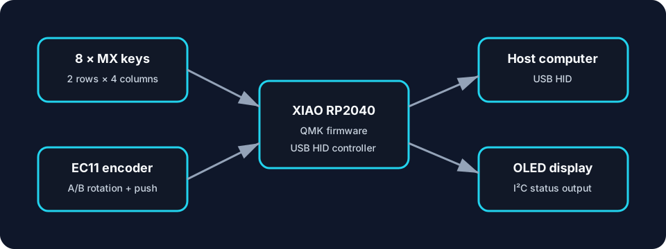
An end-to-end mechatronics build combining PCB design, embedded firmware, human-machine-interface design, and a 3D-printed enclosure. The device uses eight mechanical keys, an EC11 rotary encoder with push switch, an OLED header, and a Seeed Studio XIAO RP2040.
Status: design package complete; fabrication outputs are included. Hardware behavior must be verified on the physical assembly before the design is treated as production-ready.
| Path | Purpose |
|---|---|
PCB/ | Editable KiCad schematic and PCB sources |
CAD/case.stl | Printable enclosure mesh |
Production/gerbers.zip | PCB manufacturing outputs |
macro_firmware/ | QMK keyboard definition and keymap |
docs/BOM.csv | Bill of materials |
docs/DESIGN.md | Requirements, architecture, and engineering decisions |
docs/BUILD_GUIDE.md | Fabrication, assembly, flashing, and bring-up |
tools/design_audit.py | PCB/firmware consistency checks |
python3 tools/design_audit.pyThe audit checks the eight Cherry MX footprints, encoder switch, nine diodes, matrix dimensions, and nine populated QMK positions. It does not replace electrical-rule checking, design-rule checking, or physical bring-up.
macro_firmware into a keyboard folder in a QMK checkout.Exact commands depend on the folder name chosen inside the QMK tree. See the build guide before connecting hardware.
The PCB contains eight Cherry MX switches plus the encoder push switch: nine physical buttons total. The original firmware layout declared all ten positions of the 2 × 5 matrix and assigned a key to the unpopulated position. This version models only the nine populated positions while retaining the 2 × 5 electrical matrix.
PCB design · embedded C · QMK · RP2040 · matrix scanning · design for manufacture · CAD-to-print workflow · engineering validation
Original firmware, documentation, and project-specific design files are released under the MIT License. Third-party footprints, libraries, and tools retain their respective licenses.
| Qty | Value | Footprint | References |
|---|---|---|---|
| 9 | D | Diode_THT:D_DO-35_SOD27_P7.62mm_Horizontal | D1, D2, D3, D4, D5, D6, D7, D8, D9 |
| 8 | SW_Push_45deg | Button_Switch_Keyboard:SW_Cherry_MX_1.00u_PCB | SW2, SW3, SW4, SW5, SW6, SW7, SW8, SW9 |
| 1 | OLED_DISPLAY | Connector_PinHeader_2.54mm:PinHeader_1x04_P2.54mm_Vertical | J1 |
| 1 | RotaryEncoder_Switch | Rotary_Encoder:RotaryEncoder_Alps_EC11E-Switch_Vertical_H20mm | SW1 |
| 1 | Seeed Studio XIAO RP2040 | footprints:XIAO-Generic-Hybrid-14P-2.54-21X17.8MM | U1 |
20 parts. The full list of its parts is on this page, with links to each part's symbol and footprint where PCBKit's library has them.
From the Mahinpatelin/Macro repository on GitHub, at the commit this page was made from: the board is PCB/Macro Pad.kicad_pcb and its schematic PCB/Macro Pad.kicad_sch. PCBKit opens the board in the browser, with nothing to install.
Its repository publishes it under the MIT licence: you may reuse it on that licence's terms (keep the author's notice, and for a copyleft licence share your changes alike).


atopile/atopile
Design circuit boards with code! ✨ Get software-like design reuse 🚀, validation, version control and collaboration in hardware; starting with electronics ⚡️

davidphilipbarr/Sweep
Sweep - a small promicro based keyboard inspired by the Ferris.

rusefi/rusefi
rusefi - GPL internal combustion engine control unit

hoglet67/RGBtoHDMI
Bare-metal Raspberry Pi project that provides pixel-perfect sampling of Retro Computer RGB/YUV video and conversion to HDMI

hackclub/OnBoard
💡 Join 1,000 teenagers and make your first PCB with a $100 grant!

FreeYourStream/freedeck-hardware
all the stuff you need to build your own FreeDeck