2 layers116.8 × 30 mm
Type d
google/mozc-devices
Circuit diagrams and firmware source code for Gboard DIY keyboards
14 parts3kApache-2.0
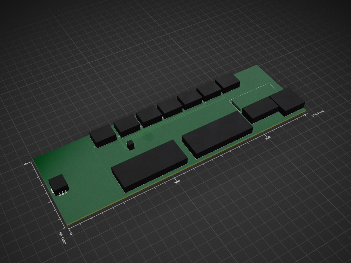
 Mag1312/Split-Flap-Machine
This hobby project focuses on the creation of a split flap display having additional features, encompassing engineering, product deisgn, web desinging and more.
Wiring Schematic is an open-source printed circuit board by Mag1312, from the Mag1312/Split-Flap-Machine repository on GitHub. It is a 2-layer board with 14 parts on 116 nets, routed with 63 tracks and 0 vias.
It belongs with the lEDs and displays and audio and music boards of this library.
This split flap machine is a hobby project by Mag, It is a device which displays time, date, weekday, weather, any word which is less than 7 letters and can even play your favourite songs from a MicroSD Card.
The Split Flap Machine's main attraction, The split flap consists of 37 flaps, 10 numbers (0-9), 26 alphabets (A-Z) and a blank flap. It is made possible mainly with the use of 28byj48 stepper motor, A4988 driver, Hall sensor and an ESP 32. The split flap drum has a small neodimium magnet which gets detected by the hall sensor and sends an update, the place where the magnet's field is not felt by the sensor, is the 0 position. Whenever something is to be displayed, the drum/spool is rotated with respect to this position to display.
The music system works from the webserver, where there are controls to play music. These controls can be used to play music from the MicroSD card.
This all works on a 10000MaH battery.
The split flap machine consists of 7 split flap units, consisting of 37 flaps, a spool and a stand. A single split flap unit uses a 28byj48 stepper motor, A4988 stepper driver, ky035 hall sensor and a ball bearing. As mentioned earlier, after the startup a calibration function runs which runs in the following process.
Rotate spool until magnet detected --> Rotate spool until magnet is not detected --> set position = 0
After which to display a character, it first checks the ascii value of the character to be displayed in a seperate array, the position of the array of the ascii value is taken. the position of array times the number of steps per flap is multiplied to get the required position to revolve to display the character. Afterwhich the motor rotates the spool until the position is achieved. There is a killswitch if the spool rotates more than 1 revolution the program fails and freezes.
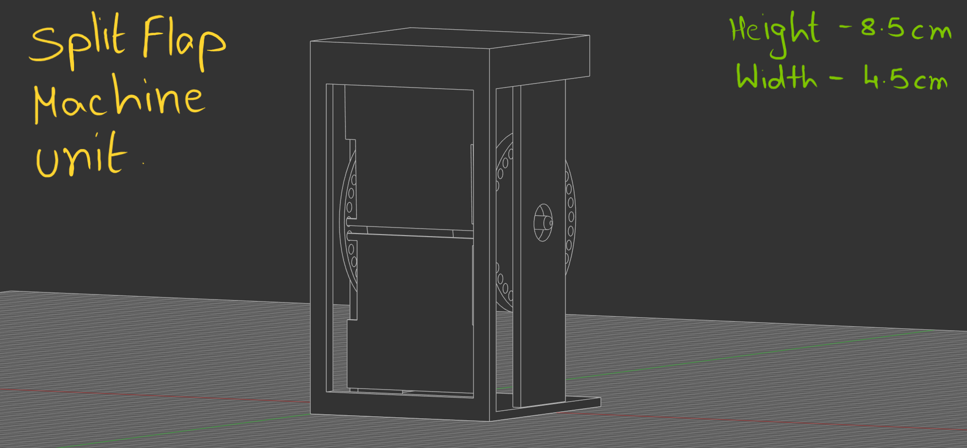
You can better understand this in my firmware, go check it out. This is the central operation around which all functions work.
The song system uses a MicroSD card, PCM5102A DAC Module, PAM8406 Amplifier and 2x 8ohm 3Watt speakers. This has been chosen for the highest quality and a mid-high battery life.
The system uses a 10000MaH battery pack with a buck converter to convert voltage.
Read Timeline.md for more understanding.
If you have any regards or have found an issue please contact +91 9346651359 (or) email to magazine2512@gmail.com.
| Qty | Value | Footprint | References |
|---|---|---|---|
| 7 | ~ | SplitFlapDisplayFootprintsLibrary:MODULE_A4988_STEPPER_MOTOR_DRIVER_CARRIER | U1, U2, U3, U12, U13, U19, U20 |
| 2 | ~ | SplitFlapDisplayFootprintsLibrary:ESP 32 S3 Devkit C1 | U16, U29 |
| 1 | R_Potentiometer | SplitFlapDisplayFootprintsLibrary:XDCR_PEC11R-4215F-S0024 | RV1 |
| 1 | ~ | SplitFlapDisplayFootprintsLibrary:PCM5102A_DAC | U21 |
| 1 | ~ | SplitFlapDisplayFootprintsLibrary:PAM_8406 | U25 |
| 1 | ~ | SplitFlapDisplayFootprintsLibrary:Buck_Converter | U4 |
| 1 | ~ | SplitFlapDisplayFootprintsLibrary:MicroSD_Module | U22 |
14 parts. The full list of its parts is on this page, with links to each part's symbol and footprint where PCBKit's library has them.
From the Mag1312/Split-Flap-Machine repository on GitHub, at the commit this page was made from: the board is Wiring Schematic/Wiring Schematic.kicad_pcb and its schematic Wiring Schematic/Full Circuit.kicad_sch. PCBKit opens the board in the browser, with nothing to install.
Its repository states no licence, so its author keeps all rights: ask Mag1312 before reusing the design.
google/mozc-devices
Circuit diagrams and firmware source code for Gboard DIY keyboards


hackclub/OnBoard
💡 Join 1,000 teenagers and make your first PCB with a $100 grant!


Twotoz/C5VRX
Ultra-minimal, zero-CPU 5.8 GHz analog FPV video receiver using ESP32-C5 Wi-Fi 6 PHY MODEM_DIAG, BitScrambler WBFM demodulation & resistor DAC CVBS

