2 layers100 × 62 mm
Magic switchboard
RincewindWizzard/magic-switchboard
A magic schwitchboard is a little box with four switches and four lamps colored in red, green, blue and yellow. The switches have got hats in the same colors.
26 parts18GPL-3.0

 mafdezmoreno/ATtiny2313_Clock_MikroC
DIY Clock. Code. PCB (KiCAD). 3D STL
Reloj Attiny2313A 3492AS is an open-source printed circuit board by mafdezmoreno, from the mafdezmoreno/ATtiny2313_Clock_MikroC repository on GitHub. It is a 2-layer board of 45.7 × 22.2 mm with 19 parts on 29 nets, routed with 140 tracks and 16 vias.
It is built around the ATTINY2313A-PU and DHT11. Its parts include 2 capacitors, 2 ICs and 1 connector. It belongs with the lEDs and displays boards and the AVR (ATmega, ATtiny) boards of this library.


DIY clock using seven-segment display, ATtiny2313A and optionaly an DHT sensor.
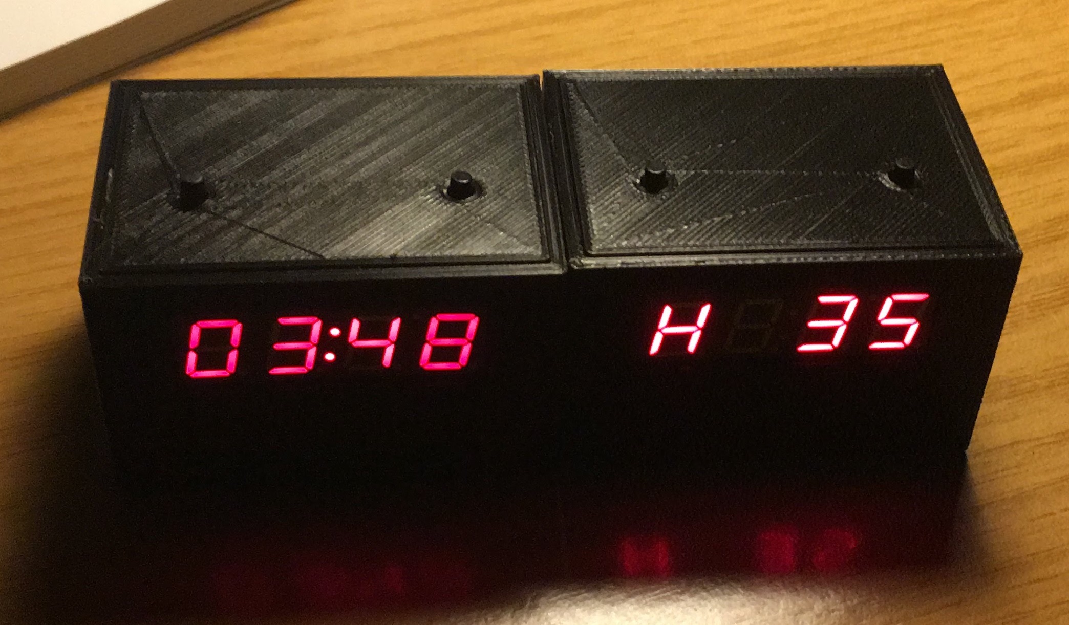
To carry out this project, it is essential to have a PCB (the one attached in this project or a similar one) in which to solder all the components.
The circuit can also be mounted in an equivalent way on a breadboard following the connection diagram.
A series of electronic components are needed. Below are the recommended components for the realization of the project. Some of them can be replaced by equivalent ones, for example: the value of the resistors, capacitors, mcu (also fucniona with the ATtiny2313), etc.
Compilation and programming tools are also needed. Below are the recommended ones
List of electronics component nedded:
| Qty | Value | Footprint | References |
|---|---|---|---|
| 5 | 560R | Resistors_SMD:R_0805_HandSoldering | R_DIG1, R_DIG2, R_DIG3, R_DIG4, R_DIG5 |
| 4 | 10K | Resistors_SMD:R_0805_HandSoldering | R_H1, R_M1, R_RESET1, R1 |
| 2 | 22pF | Capacitors_SMD:C_0805_HandSoldering | C1, C2 |
| 1 | ATTINY2313A-PU | Housings_DIP:DIP-20_W7.62mm | U1 |
| 1 | Conn_01x02_Male | Connectors_Molex:Molex_KK-6410-02_02x2.54mm_Straight | J1 |
| 1 | Crystal | Crystals:Crystal_HC49-4H_Vertical | Y_11.0592MHZ1 |
| 1 | DHT11 | Connectors_Molex:Molex_KK-6410-04_04x2.54mm_Straight | DHT_1 |
| 1 | DISPLAY_3492AS_16pin | MisHuellas:Display_40mmx13mm_16Pin | U3 |
| 1 | ISP_Conector | Connectors_Molex:Molex_NanoFit_2x03x2.50mm_Straight | ISP1 |
| 1 | SW_HORA | Buttons_Switches_THT:SW_Tactile_SPST_Angled_PTS645Vx83-2LFS | SW_H1 |
| 1 | SW_MINUTO | Buttons_Switches_THT:SW_Tactile_SPST_Angled_PTS645Vx83-2LFS | SW_M1 |
RincewindWizzard/magic-switchboard
A magic schwitchboard is a little box with four switches and four lamps colored in red, green, blue and yellow. The switches have got hats in the same colors.


GrzegorzewskiSzymon/Controlled-UV-lamp-for-making-PCBs
This project is originally written for ATtiny2313A with external 16MHz oscilator.


ondras12345/pm-sensor
SPS30-based PM2.5 particulate matter sensor with RS485

It measures 45.7 × 22.2 mm and has 2 copper layers, 1.6 mm thick.
19 parts, built around the ATTINY2313A-PU and DHT11. The full list of its parts is on this page, with links to each part's symbol and footprint where PCBKit's library has them.
From the mafdezmoreno/ATtiny2313_Clock_MikroC repository on GitHub, at the commit this page was made from: the board is PCB_KiCAD/Reloj_Attiny2313A_3492AS.kicad_pcb. PCBKit opens the board in the browser, with nothing to install.
Its repository states no licence, so its author keeps all rights: ask mafdezmoreno before reusing the design.