

2 layers85.6 × 54 mm
PCB Business Card
Sealflux/PCB_Business_Card
A business card that lights up when you tap it with your phone. No battery. It just steals power from the phone's NFC radio.
17 partsMIT
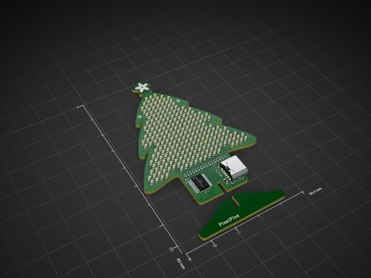
 machmar/pixelpine
PixelPine: a 7 cm PCB Christmas tree with 240 charlieplexed LEDs and a personality (KiCad, simulator, firmware sizing, docs)
Pixelpine is an open-source printed circuit board by machmar, from the machmar/pixelpine repository on GitHub. It is a 2-layer board of 50.5 × 83 mm with 271 parts on 39 nets, routed with 1,658 tracks and 142 vias.
It is built around the PY32F003F18P6TU and XL-1608WWC-06. Its parts include 240 diodes, 19 resistors, 2 capacitors, 1 IC and 1 connector.
KTE Project 1 · design-for-manufacture study · rev A · 2026-09-23
A chubby, cute, 70 mm tall PCB tree covered in 240 warm-white 0603 LEDs on a 2.12 mm grid. The LEDs are
charlieplexed on 16 pins of a $0.13 Puya PY32F003 (Cortex-M0+, 64 KB flash) with software PWM. It runs from USB-C and slots into a
PCB stand fin. The tree is a character, Pine, whose job is showing light shows. He's bad at it: he daydreams,
naps, gets grumpy and gets excited to show you things. You interact with him through the capacitive star, which
senses tap, pet, press, a front-and-back squeeze and tickles. The product firmware runs on the first boards and
matches the simulator frame for frame (firmware/pixelpine/).
Landed cost ≈ €3.2 at 1 000 pcs, €2.0 at 10 000 pcs; suggested shelf price €12.90.
Try Pine in your browser: machmar.github.io/pixelpine (the animation simulator).
| Front | Back |
|---|---|
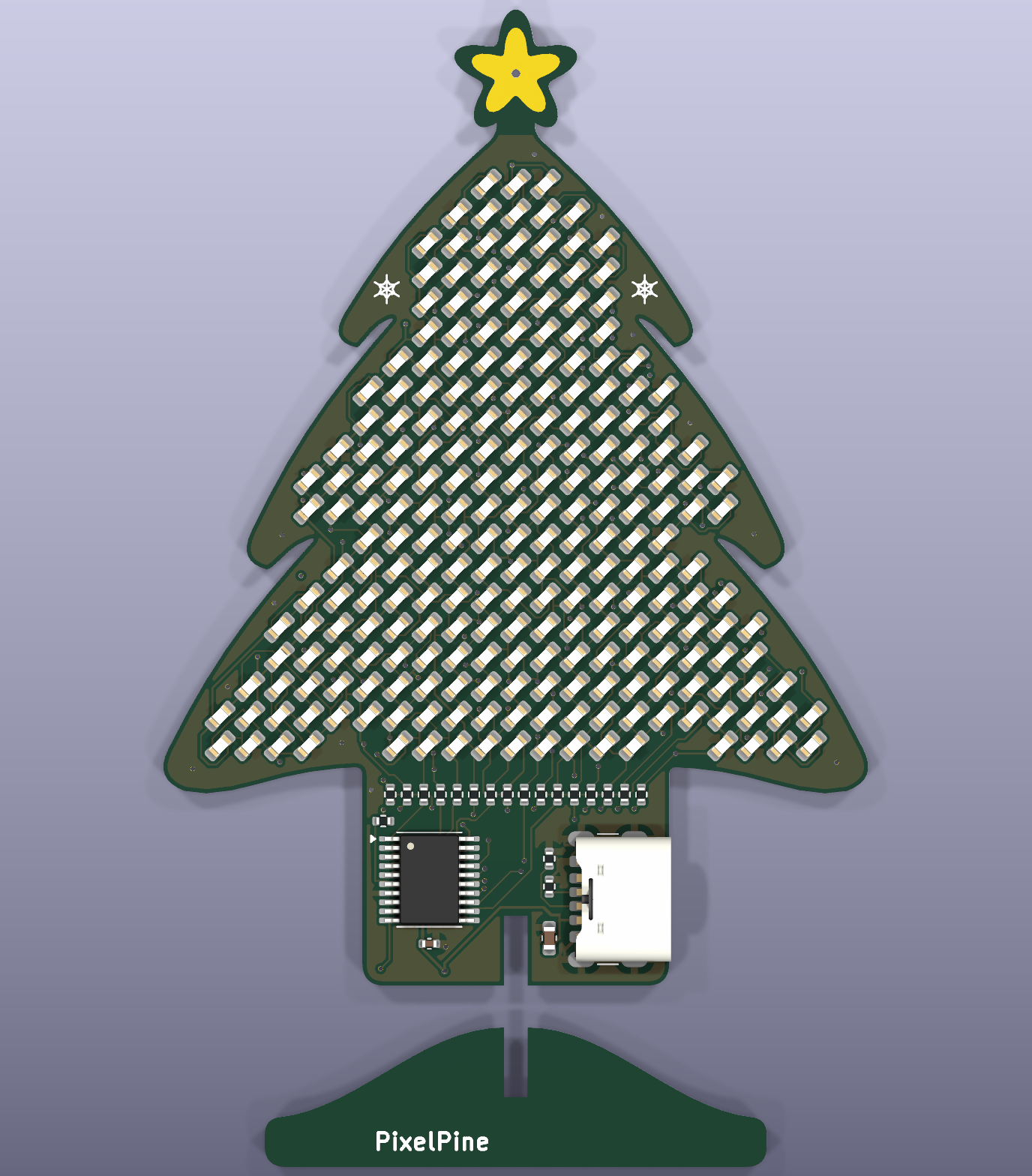 | 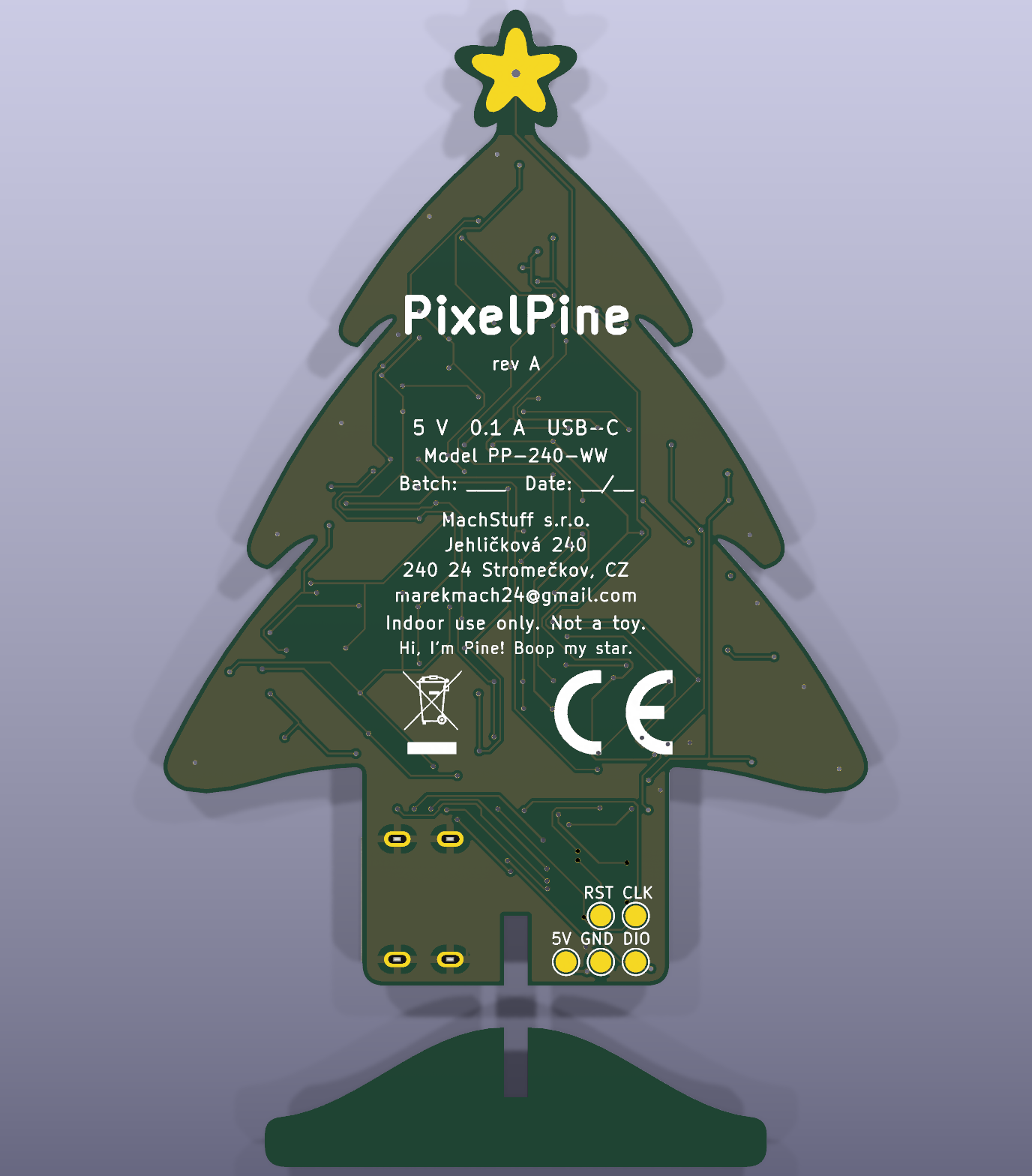 |
| You asked for | Where |
|---|---|
| Schematic | hardware/pixelpine_schematic.pdf · KiCad 10 project hardware/pixelpine.kicad_pro (ERC: 0 errors, 0 warnings) |
| PCB shape and layout | hardware/pixelpine.kicad_pcb: outline, stand fin, all 267 parts (+2 logo marks) placed with nets, silkscreen, CE/WEEE marks, routed on 2 layers (Freerouting, then finished by hand in KiCad: GND pour on both layers, 142 vias). DRC: 0 unconnected, schematic parity 0 issues; 2 cosmetic starved thermal notes (see the order guide). The LEDs sit in a routing-friendly arrangement: see LED arrangement |
| BOM (LCSC / JLCPCB) | docs/bom.md · JLC upload files hardware/production/jlc_bom.csv, jlc_cpl.csv |
| Order files | hardware/production/: Gerber + drill zips for the tree (PCB + assembly) and the stand fin (bare PCB), BOM/CPL, 3D previews, and an order guide with every JLC setting and what to check in the placement preview |
| PC app to preview the animations | simulator/index.html, live at machmar.github.io/pixelpine (published from simulator/ by .github/workflows/pages.yml): open it in any browser; works offline apart from fonts. Pine runs live: touch his star (hover / click / hold / shift / ctrl / fast clicks) and watch his feelings change. Preview mode plays any show, face or transition. Includes an electrical model of the charlieplex (current sag, PWM depth, refresh, pin current) |
| Pine: character, faces, transitions, gestures | docs/animations.md: behaviour state machine, emotions, 15 light shows, 16 faces, 6 transitions, touch gestures, RAM/flash budget |
| Market analysis | docs/market-analysis.md |
| EU certification setup | docs/eu-compliance/: applicability matrix, EMC test plan, technical file + risk assessment, DoC template, labels and leaflet (EN/CZ) |
| Final price analysis incl. assembly | docs/cost-analysis.md, generated by docs/cost_model.py |
| Connectivity & power consumption | docs/power-and-connectivity.md |
| Product firmware (beyond the brief) | firmware/pixelpine/: the simulator ported to C and running on the board: 59 KB of 63 KB flash, 7.0 KB of 8 KB RAM, 50 fps, 122 Hz 10-bit BCM scan. Checked frame by frame against the simulator's own JavaScript: Pine's state machine and emotions identical in every whole-Pine test, LED levels within 1 step of 255 on ≥ 99.99 % of LED-frames there (per show: 93–100 %, fireflies lowest). Touch calibrated on the board; room-light sensing isn't possible on rev A (and how rev B fixes it); a whole-tree touch field was tried and dropped (why). Flashing: firmware/flash/ |
| Firmware fit check | firmware/sizetest/: real compile of all shows, faces, brain and drivers for both MCUs. The original CH32V003 overflowed (20.9 KB of 16 KB), so the MCU was switched to the PY32F003F18P6: 17.2 KB of 64 KB flash (27 %), 1.9 KB of 8 KB RAM (23 %), built with the Arm GNU Toolchain. See docs/animations.md |
| Design spec | docs/superpowers/specs/2026-09-23-pixelpine-design.md |
| All docs as PDF | docs/pdf/PixelPine-documentation.pdf: everything above in one linked PDF (cover, contents), plus one PDF per doc in docs/pdf/. Regenerate with python docs/export_pdfs.py after editing a doc |
| LEDs | 240 × XL-1608WWC-06 (0603, 2500–3000 K) at 45°, 2.12 mm pitch |
| MCU | Puya PY32F003F18P6 (TSSOP-20, pinout 1, 24 MHz internal oscillator): 16 charlieplex lines (incl. SWD pins and BOOT0) + ADC touch star (PA7) + NRST; SWD programming |
| Character | 6 emotions (energy, focus, mood, annoyance, excitement, bond in flash), 16 faces, 6 transitions |
| Parts | 263 placements, 8 line items, 552 SMD joints, single-sided |
| PCB | 2-layer FR-4 1.6 mm, LF-HASL, JLC standard process (0.10 mm tracks and spaces at the narrowest, 0.3 / 0.4 mm vias); 1658 track segments (1991 mm), 142 vias, GND pour on both layers, 0 unrouted. Tree 50.5 × 70 mm, stand fin 36 × 10 mm |
| Supply | USB-C 5 V, 3–12 mA typical (≈ 7 mA average), 19 mA max → ≤ 0.1 W |
| Light | ≈ 2 lm total, so outside the EU light-source ecodesign/energy-label scope |
| Pin current | ≤ 16.2 mA per GPIO by design (20 mA rated) |
| PWM | 8-bit binary-code modulation, 16 phases, 122 Hz refresh (the product firmware: 10-bit, same refresh) |
| CE route | EMC 2014/30/EU (EN IEC 55015 + EN 61547) + RoHS; GPSR, WEEE, PPWR, REACH obligations |
The 240 LED positions are a fixed 2.12 mm grid, but which anode/cathode pair sits at which position is a free choice,
and it decides whether the board can be routed at all. The first version interleaved the pairs (anode = n mod 16),
which leaves every one of the 480 LED pads as an island of its own, and Freerouting stalled with 76 connections still
open after 87 minutes.
The 45° LEDs form a "brick" lattice with only ~0.55 mm between neighbouring pads. If two neighbouring pads are on the
same line net, a tiny F.Cu bridge joins them for free, so a net can be a few big copper islands instead of 30 loose
pads. hardware/scripts/optimize_leds.py (simulated annealing, C core in
optimize_leds.c) arranges the 240 pairs for exactly that: 480 separate pads became 141 islands, only the links between
islands need real wiring, and the board routes on 2 layers in about 2 minutes (it also stopped needing the 4 layers
that the old arrangement was thought to need). The result is hardware/led_assignment.json,
committed; geometry.py reads it, so the schematic, PCB, simulator map and firmware tables all follow from it. Every
LED keeps the same orientation; the optimiser can also turn LEDs round by 180° (--flip) for ~15 % fewer islands, but
that wasn't needed.
Side effect: neighbouring LEDs now sometimes share an anode line (17 % of the LED pairs closer than 3.2 mm, against
6 % with the old interleaving), so a lit blob loads some scan phases harder than before. The numbers are in
docs/power-and-connectivity.md.
Since 2026-10-01 the board is finished by hand in KiCad (GND pour, extra vias).
build_all.pywould regenerate it from the scripts and drop those edits, so it now stops unless you pass--regenerate. For order files runexport_gerbers.py(KiCad's Python) andexport_fab.py; seehardware/production/README.md.
Everything in hardware/ was generated from one geometry module, so it stays consistent:
python hardware/scripts/build_all.pygeometry.py (outline, LED grid, charlieplex map from led_assignment.json) → gen_footprints.py → gen_sch.py
(+ ERC, netlist check) → gen_pcb.py (KiCad's bundled Python) → route.py (Freerouting, ~2-5 min; if connections stay
open it routes again from scratch, up to 4 runs) → DRC and parity → 3D renders → JLC BOM/CPL. It also refreshes
simulator/led_map.js, so the simulator always shows the real LED positions. After editing the outline, run
python hardware/scripts/geometry.py --search and paste the new pitch into GRID_PITCH, then
python hardware/scripts/optimize_leds.py (needs a C compiler, 10–20 min) to re-arrange the LEDs for the new grid.
The firmware's per-LED tables come from the same map: python firmware/pixelpine/gen_tables.py, then
python firmware/pixelpine/build.py flash builds and programs a board, and python firmware/pixelpine/test/compare.py
checks the firmware against the simulator.
Order files are ready: hardware/production/README.md. At order time, check
LCSC stock for the 240 LEDs per board and look at the LED polarity and U1 pin 1 in JLC's placement preview.
firmware/flash/) and runs Pine (firmware/pixelpine/).
Still open: touch thresholds measured on one board and one hand (measure a batch); the EMC worst-case and
production-test firmware builds.firmware/pixelpine/README.md).firmware/pixelpine/README.md). The star
is the touch control.Done: PCB routed on 2 layers (LED arrangement optimised for it, DRC clean), manufacturer name, address (Jehličková 240, 240 24 Stromečkov: made up for the school project, replace it with the registered address for a real product) and e-mail on the product, U1 and J1 placement orientation checked, MCU choice final (PY32F003F18P6, kept over the cheaper F002A for firmware-update headroom).
| Qty | Value | Footprint | References |
|---|---|---|---|
| 240 | XL-1608WWC-06 | PixelPine:LED_0603_Dense | D1, D10, D11, D100, D101, D102, D103, D104, D105, D106, D107, D108, D109, D110, D111, D112 +224 |
| 16 | 100 | Resistor_SMD:R_0402_1005Metric | R1, R2, R3, R4, R5, R6, R7, R8, R9, R10, R11, R12, R13, R14, R15, R16 |
| 2 | 5.1k | Resistor_SMD:R_0402_1005Metric | R17, R18 |
| 1 | +5V | TestPoint:TestPoint_Pad_D1.5mm | TP1 |
| 1 | 100n | Capacitor_SMD:C_0402_1005Metric | C2 |
| 1 | 10u | Capacitor_SMD:C_0603_1608Metric | C1 |
| 1 | 1k | Resistor_SMD:R_0402_1005Metric | R19 |
| 1 | CE-Logo_8.5x6mm_SilkScreen | Symbol:CE-Logo_8.5x6mm_SilkScreen | LOGO1 |
| 1 | GND | TestPoint:TestPoint_Pad_D1.5mm | TP2 |
| 1 | NRST | TestPoint:TestPoint_Pad_D1.5mm | TP6 |
| 1 | PY32F003F18P6 | Package_SO:TSSOP-20_4.4x6.5mm_P0.65mm | U1 |
| 1 | STAR | PixelPine:TouchStar | TP4 |
| 1 | SWCLK | TestPoint:TestPoint_Pad_D1.5mm | TP5 |
| 1 | SWDIO | TestPoint:TestPoint_Pad_D1.5mm | TP3 |
| 1 | TYPE-C 6P | PixelPine:USB_C_SHOUHAN_TYPE-C-6P | J1 |
| 1 | WEEE-Logo_4.2x6mm_SilkScreen | Symbol:WEEE-Logo_4.2x6mm_SilkScreen | LOGO2 |
It measures 50.5 × 83 mm and has 2 copper layers, 1.6 mm thick.
271 parts, built around the PY32F003F18P6TU and XL-1608WWC-06. The full list of its parts is on this page, with links to each part's symbol and footprint where PCBKit's library has them.
From the machmar/pixelpine repository on GitHub, at the commit this page was made from: the board is hardware/pixelpine.kicad_pcb and its schematic hardware/pixelpine.kicad_sch. PCBKit opens the board in the browser, with nothing to install.
Its repository states no licence, so its author keeps all rights: ask machmar before reusing the design.
Sealflux/PCB_Business_Card
A business card that lights up when you tap it with your phone. No battery. It just steals power from the phone's NFC radio.

zdeager/powermod
Machine-generated PCB design for a Raspberry Pi Zero 2 W power scheduler / UPS / battery board. The electrical design is defined in code (netlist.py); the board was laid out and routed with the scripted KiCad +…


profdc9/RFBitBanger
A QRP digital transceiver created from readily available parts for off-the-grid maintenance

UzixLS/mist1010-board
10x10cm PCB variant of MIST FPGA project for G738/G706 enclosure


