Skip to the content
2 layers25.4 × 25.4 mmTTGO T7-V1.5 BNO085 expansion board, the printed circuit board in 3D

TTGO T7-V1.5 BNO085 expansion board

m9cd0n9ld/IMU-VR-Full-Body-Tracker125

Inertial Measurement Unit (IMU) based full body tracker for Steam VR.

Size
25.4 × 25.4 mm
Copper layers
2
Thickness
1.6 mm
Parts
2
Nets
25
Pads
30
Tracks, vias
15, 2
Routed
Yes
KiCad
KiCad 5 (file 20171130)
Created
13 Jun 2021
Updated
29 Jan 2024

Overview

TTGO T7-V1.5 BNO085 expansion board is an open-source printed circuit board by m9cd0n9ld, from the m9cd0n9ld/IMU-VR-Full-Body-Tracker repository on GitHub, published under the MIT licence. It is a 2-layer board of 25.4 × 25.4 mm with 2 parts on 25 nets, routed with 15 tracks and 2 vias.

It belongs with the sensors and measurement boards and the ESP32 boards of this library.

README

README.md

IMU-VR-Full-Body-Tracker

Inside-out full body tracker for Steam VR based on ESP32 with BNO080/085 IMU.
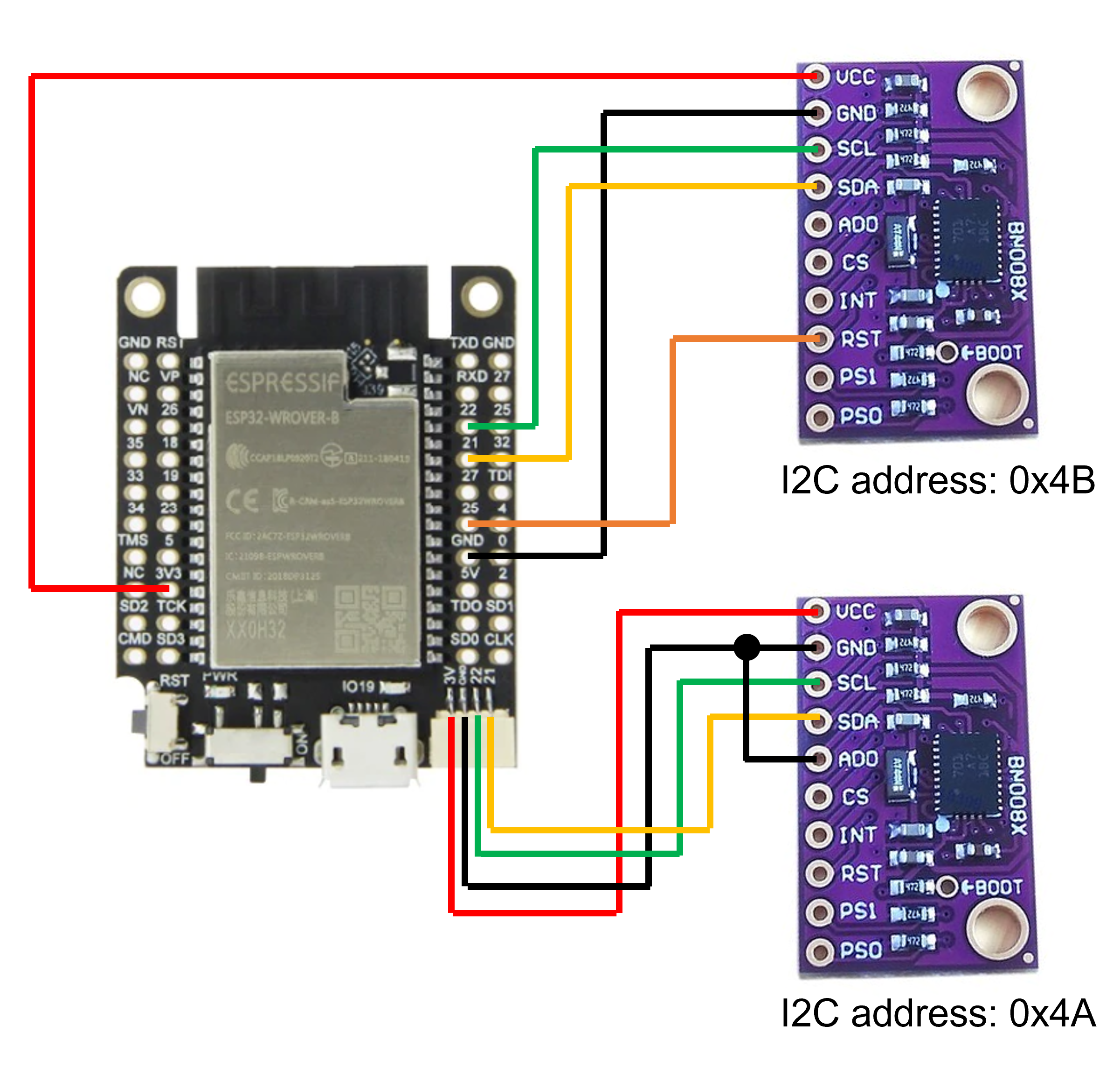
Support up to 2 BNO08X IMUs per ESP32 via I2C communication.
No base station is required, completely wireless using WiFi UDP.
Should be compatible with any VR headset that supports Steam VR.

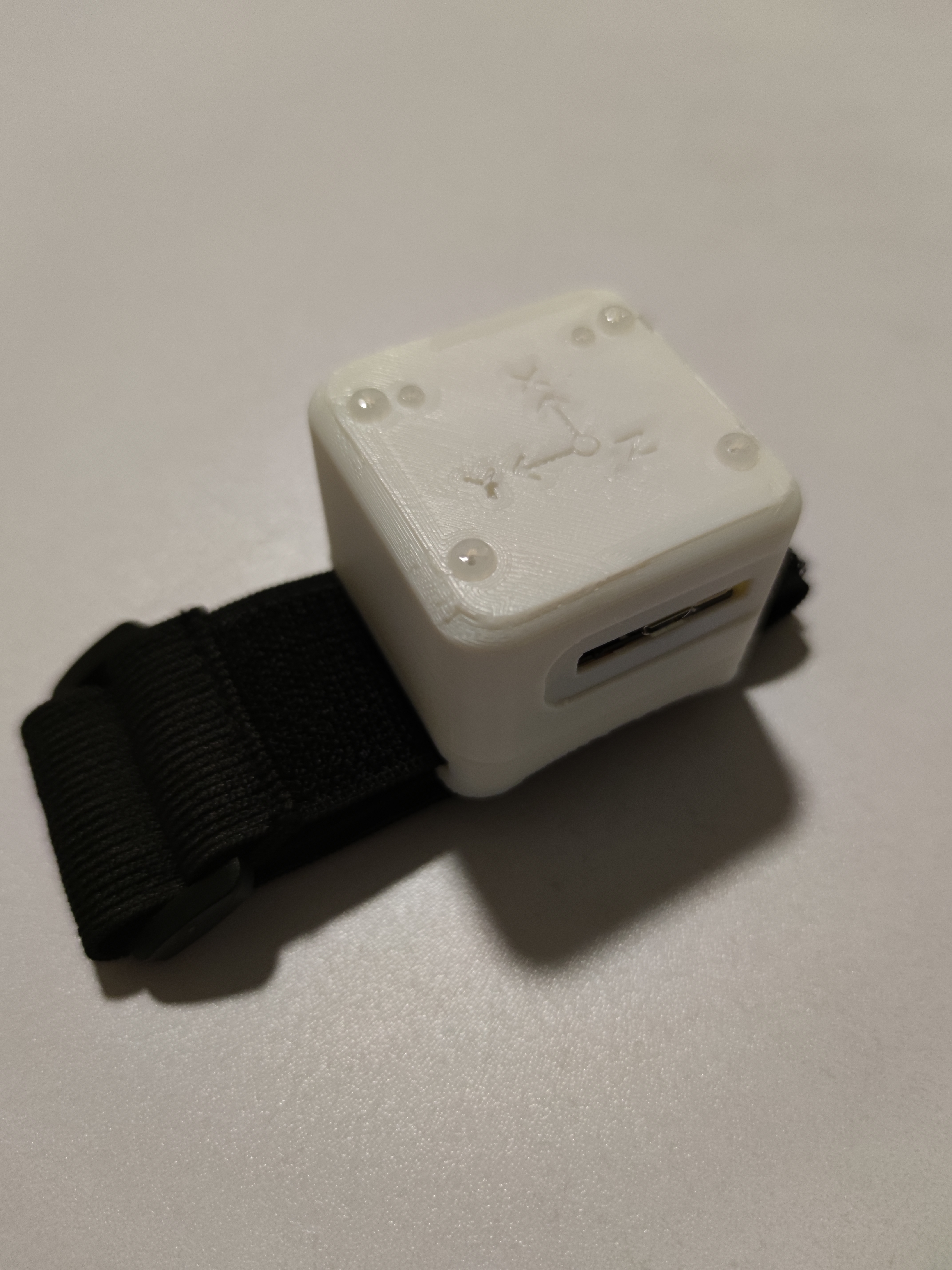
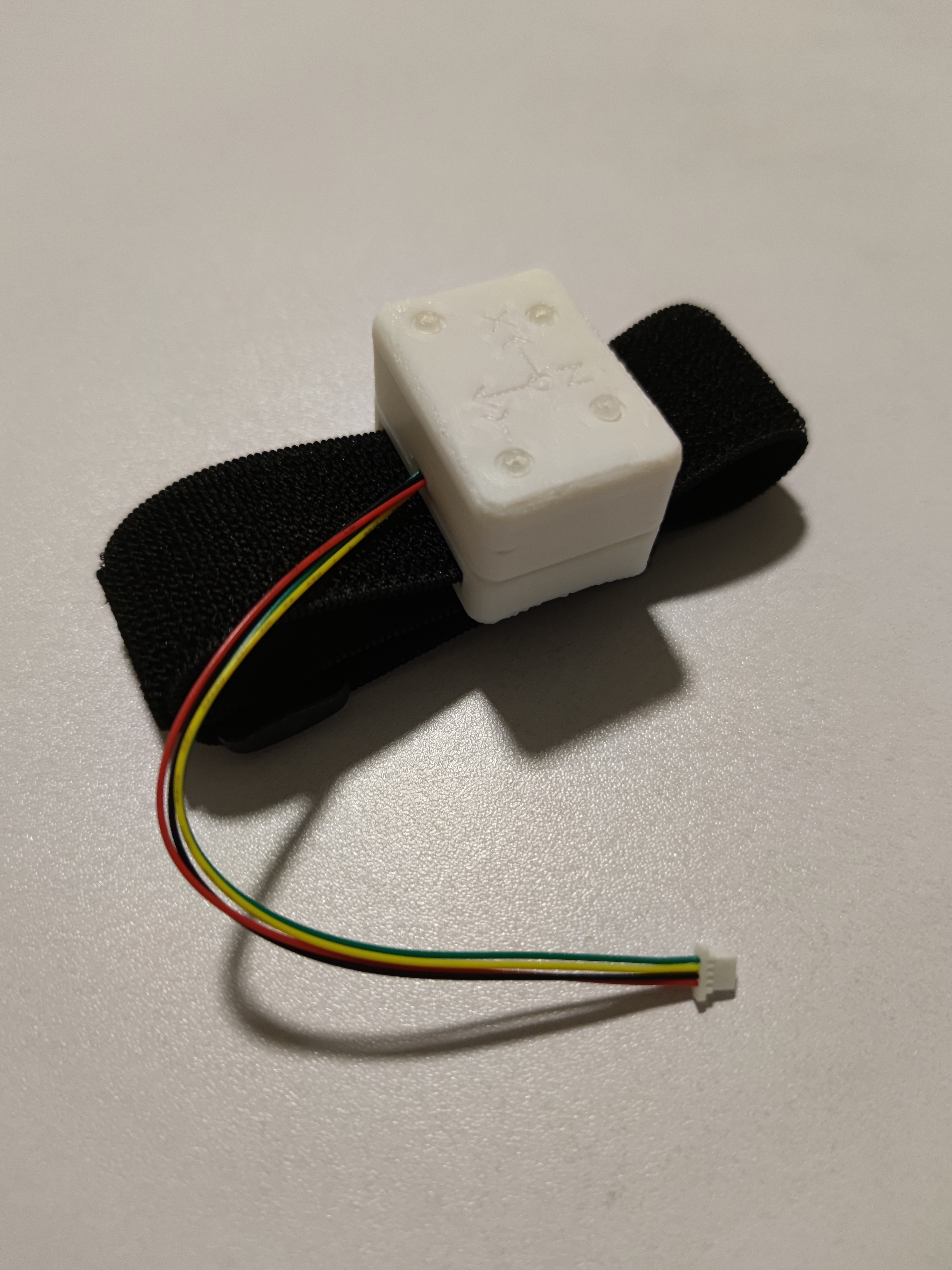
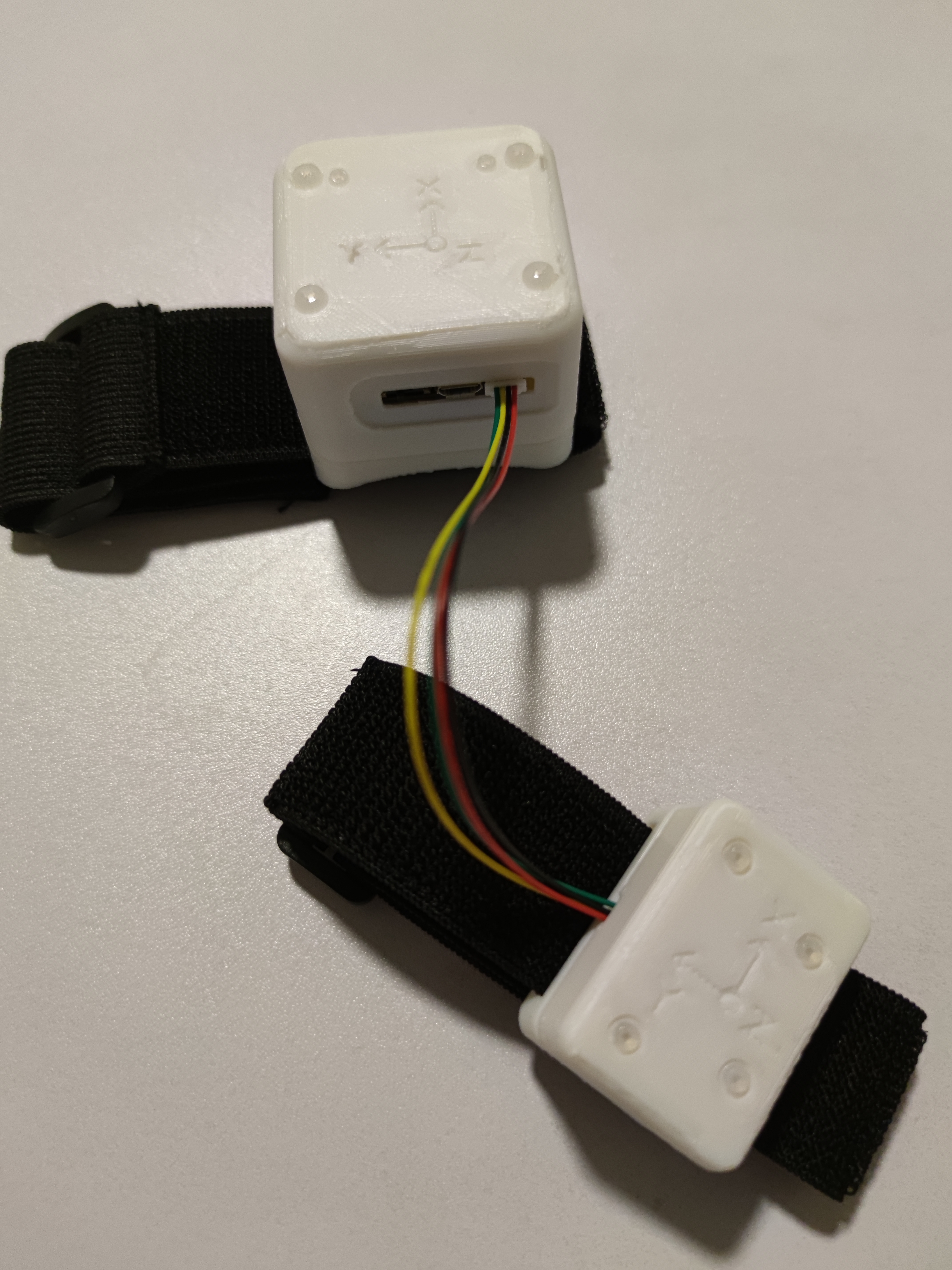
Hardware Example

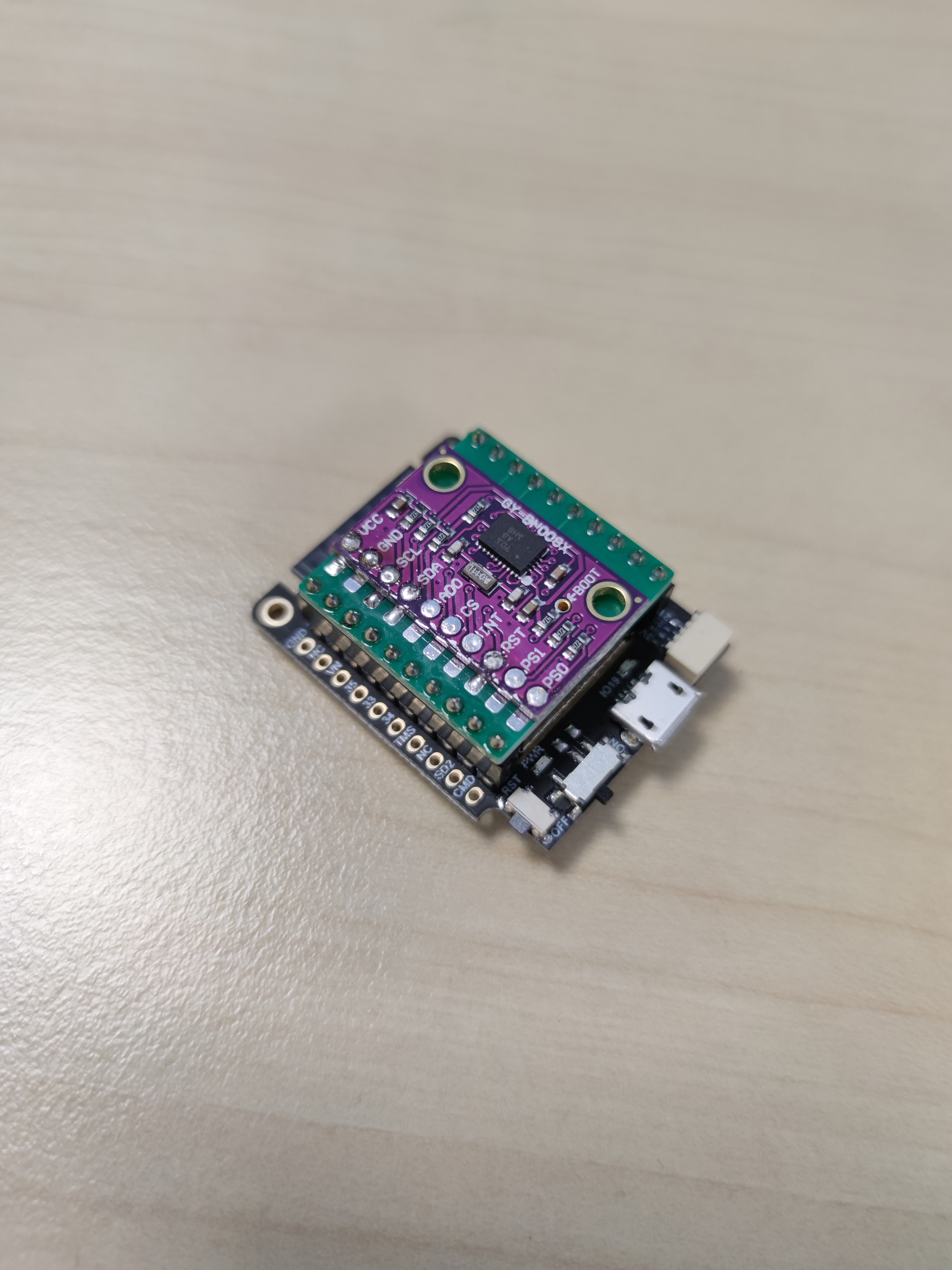
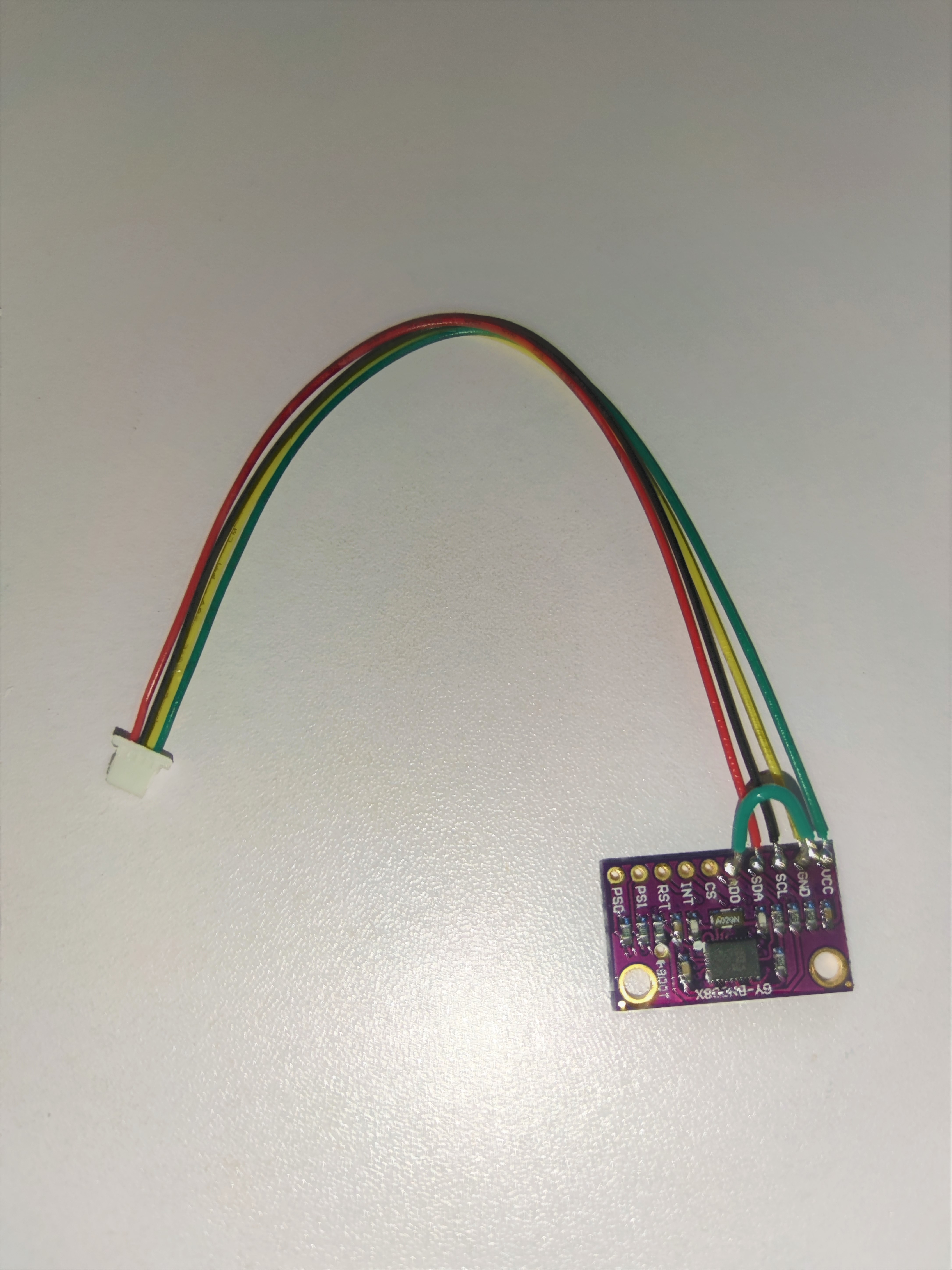
LILYGO® TTGO T7 V1.5 Mini32 ESP32-WROVER-B with GY-BNO08X

Instruction

  1. Extract steamvr.driver.zip and copy imuFBT folder to (Steam directory)\steamapps\common\SteamVR\drivers.
  2. Extract esp32.sketch.zip, edit the settings (pin settings, etc.) in esp32_settings.h file.
  3. Upload the sketch to ESP32 microcontroller with Arduino IDE (SparkFun_BNO080_Arduino_Library Arduino library is required).
  4. Extract desktop.server.zip. Add imufbtserver.exe and backend/imuFBTServerBackend.exe to Windows firewall exception list to allow UDP to work properly.
  5. Run the imufbtserver.exe (might trigger antivirus false positive, known problem for unsigned PyInstaller exe files).
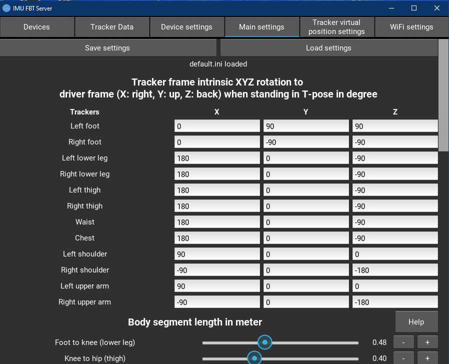
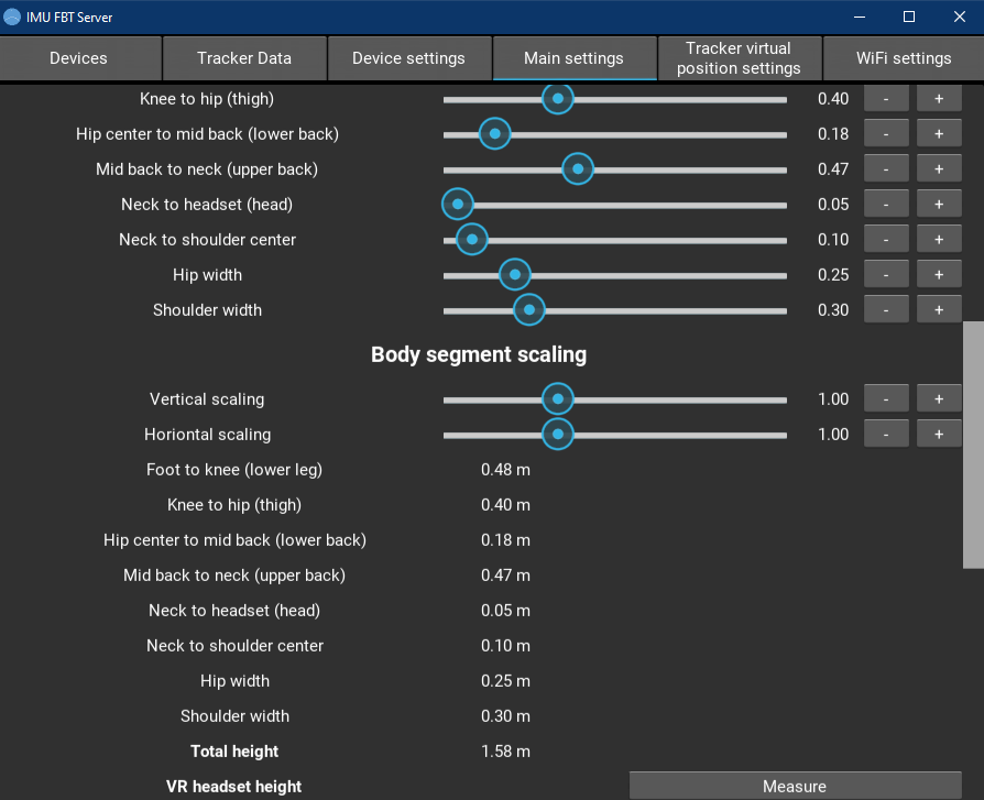
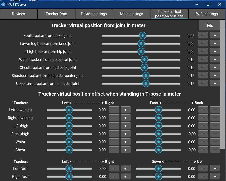
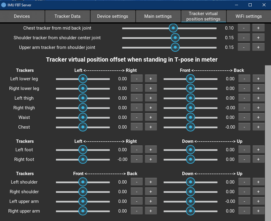
  6. Set the tracker sensor frame to driver frame (X right, Y up, Z back) XYZ intrinsic rotation based on the mounting orientation, body segment length, tracker virtual position and offset settings when standing in T-pose** in Main settings and Tracker virtual position settings tab.
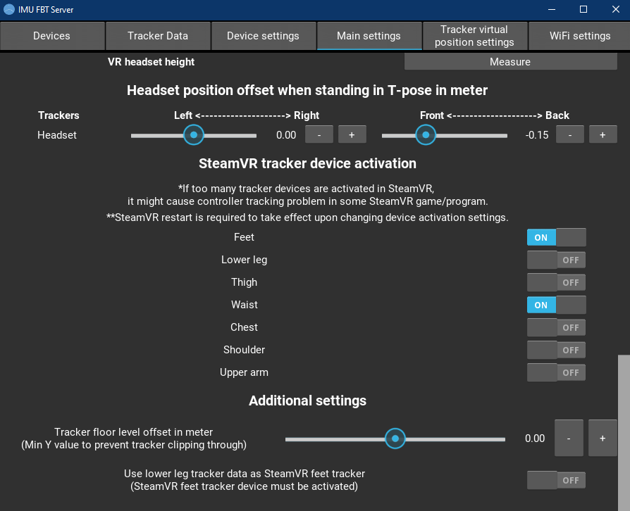
  7. Activate required tracker devices to be output to SteamVR. In some SteamVR game/program, the hand controllers might lose tracking or not working if too many tracker devices are activated.
  8. Set the tracker floor level offset (tracker min Y value to prevent clipping) if necessary.
  9. Enable lower leg tracker data as SteamVR feet tracker if want to use lower leg tracker as foot role. Feet tracker device must still be activated.
  10. Save the settings by pressing Save settings button or load an existing saved settings by pressing Load settings button in Main settings tab. The last saved/loaded settings will be automatically loaded in the next instance.

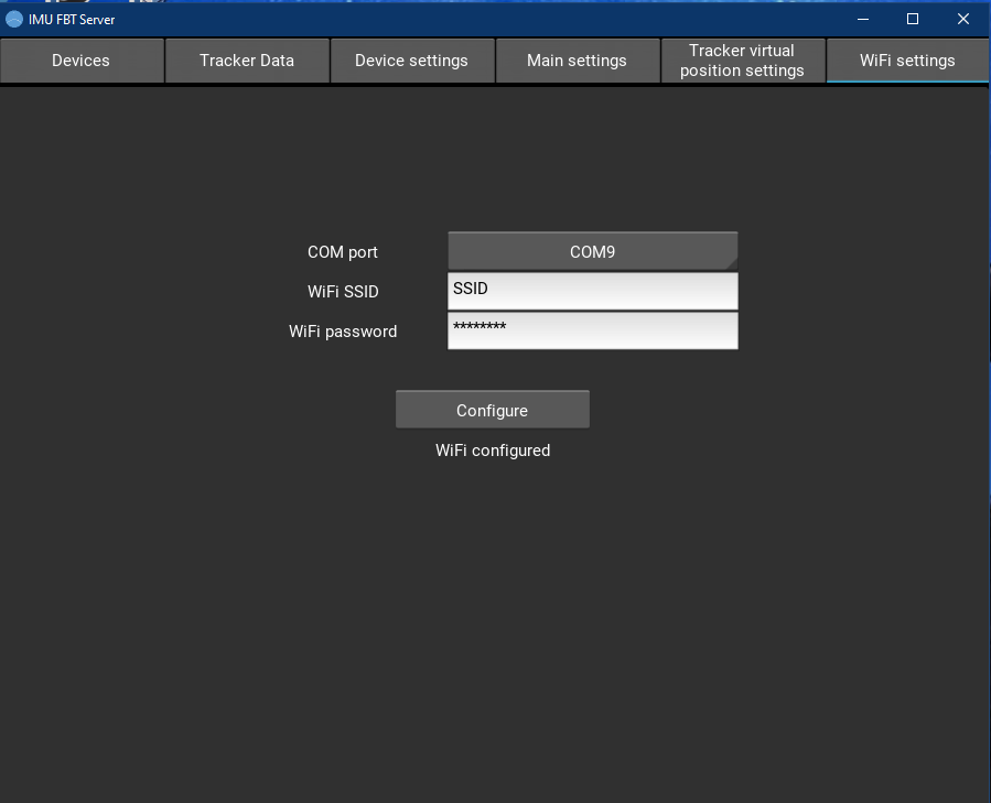
  1. Plug in USB cable to ESP32 and set the WiFi credential in WiFi Settings tab.

  1. Once WiFi credential is configured, unplug the USB cable and power cycle the ESP32 to establish WiFi connection.
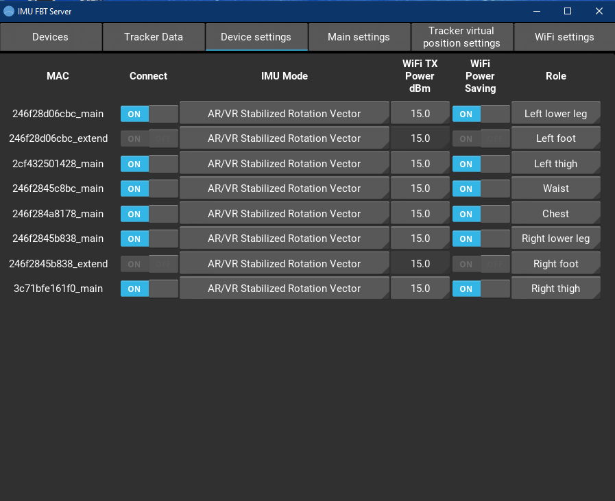
  2. The trackers will be listed in Device settings tabs.
  3. Set the IMU mode, WiFi TX power, WiFi power saving mode and role of the trackers in Device settings tab.

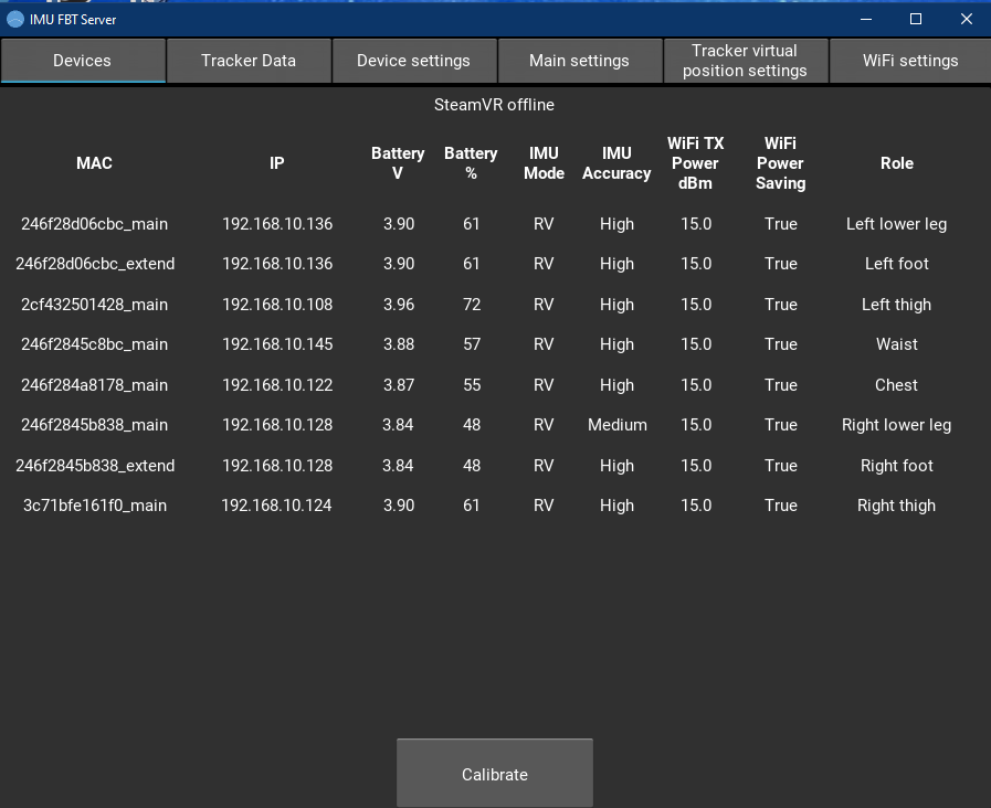
  1. Click Connect slider, and the trackers with correct settings will be shown in Devices tab.
  2. Save the settings in Main settings tab to save the device settings.

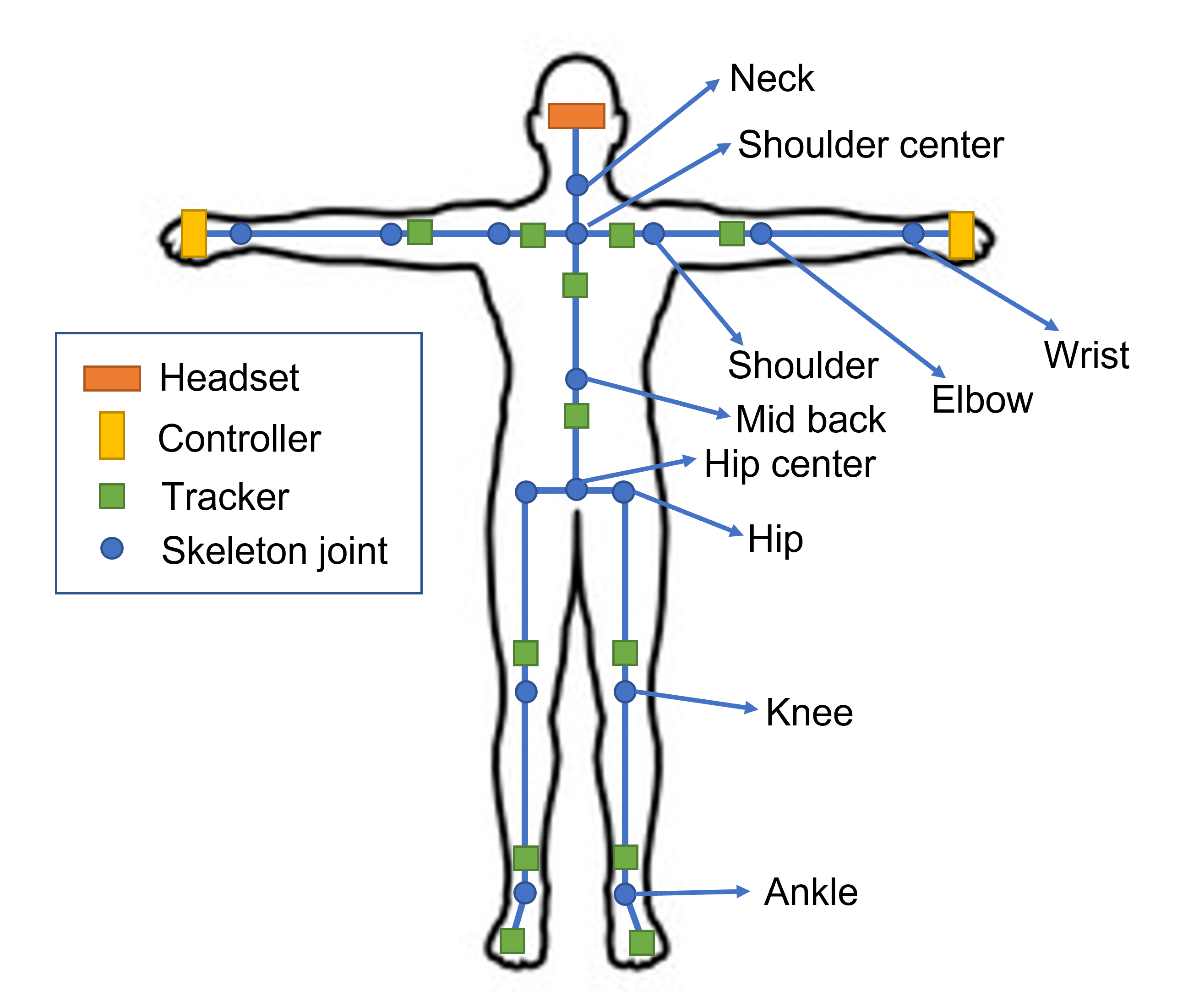
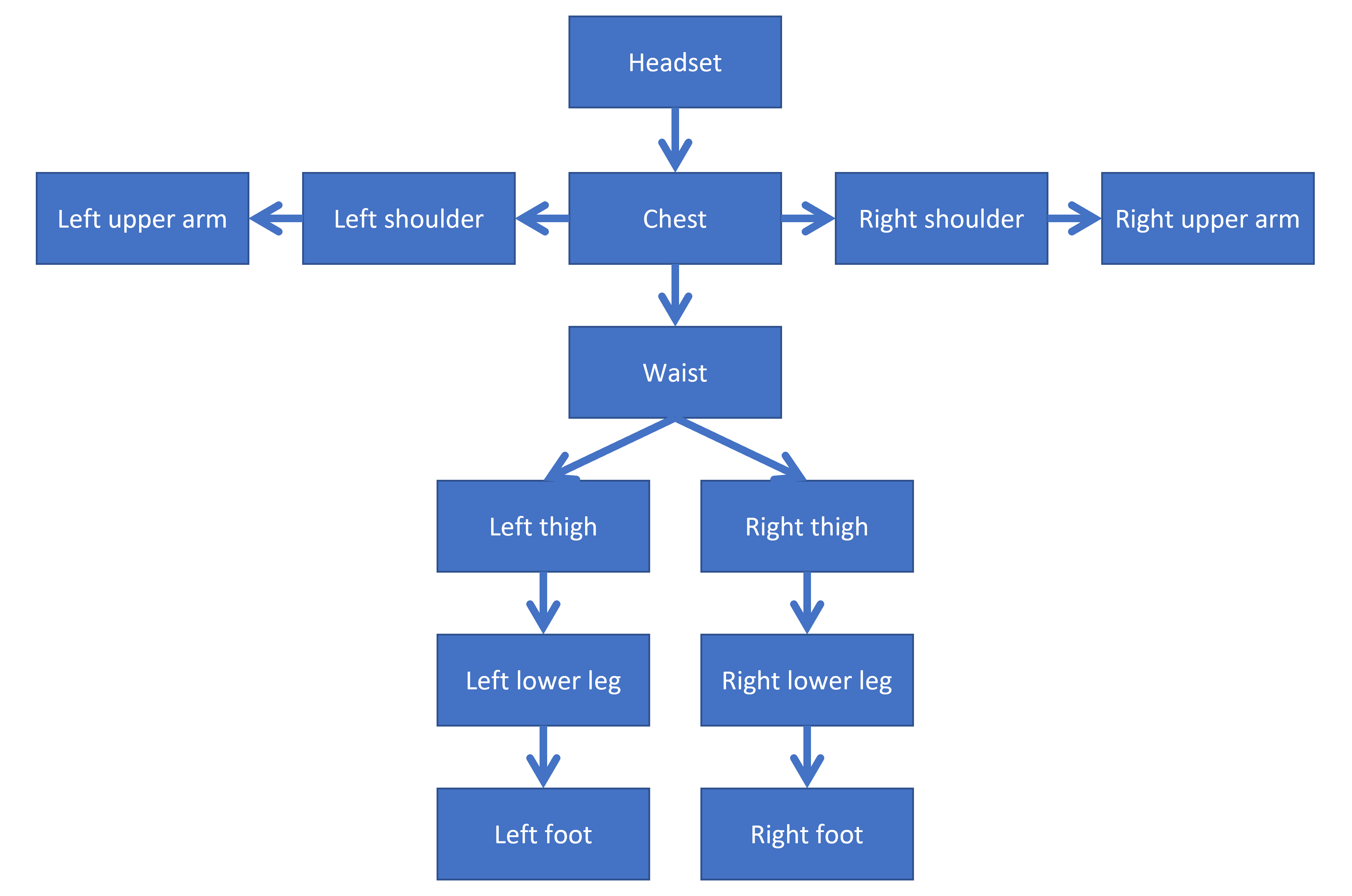
  1. Mount the trackers according to the following diagram. For feet/leg tracking, chest tracker, waist tracker, thigh trackers and lower leg trackers are required. Feet trackers are optional. For elbow tracking, chest tracker, shoulder trackers and upper arm trackers are required.

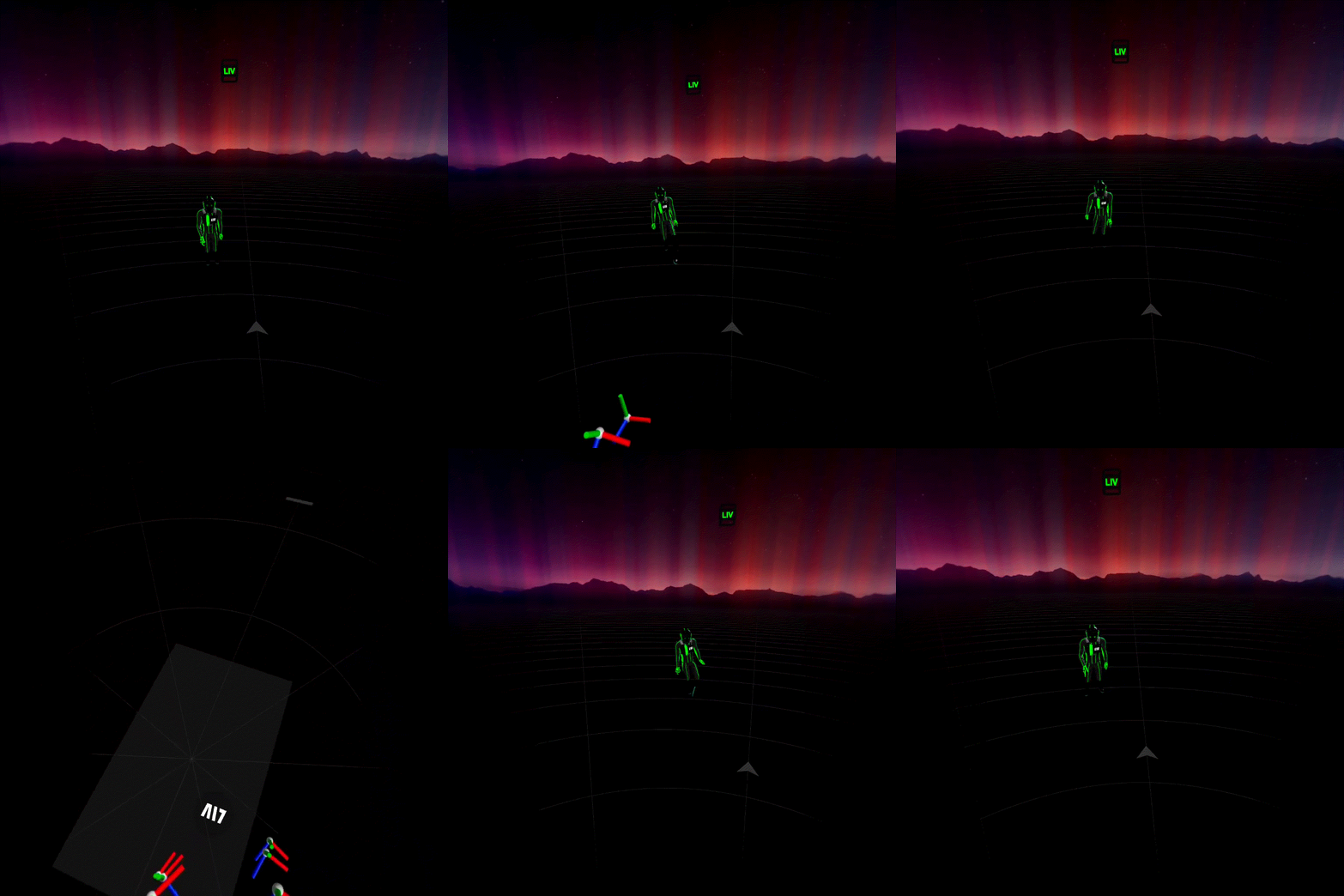
  1. Open SteamVR. The top of the Devices tab will show SteamVR online when SteamVR is detected.
  2. The trackers will be shown in SteamVR environment at weird position and orientation on startup.
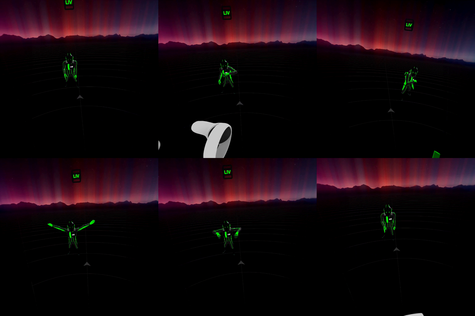
  3. Stand in T-pose**, then press Calibrate button in Devices tab to realign/calibrate the trackers.

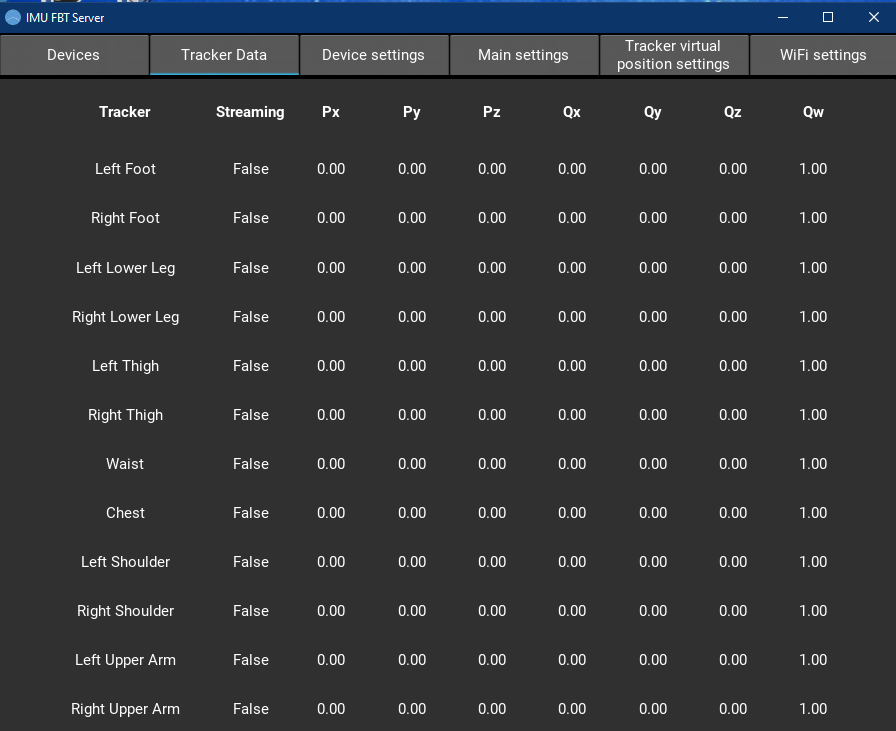
  1. Tracker output data can be seen on Tracker Data tab.

  1. Done!

**Stand straight look forward with feet pointing forward and hip-width apart in T-pose with palm facing down.

Parts

2
QtyValueFootprintReferences
1GY-BNO08XimuFBT_PCB_components:GY-BNO08XG1
1TTGOT7V1.5imuFBT_PCB_components:TTGO_T7_V1.5T1

Similar boards

  • 2 layers37 × 19 mmPassive rpi hub75-adapter, the printed circuit board in 3D

    Passive rpi hub75-adapter

    hzeller/rpi-rgb-led-matrix

    Controlling up to three chains of 64x64, 32x32, 16x32 or similar RGB LED displays using Raspberry Pi GPIO

    2 parts4.4kGPL-2.0
  • 2 layersDiode template, the printed circuit board in 3D

    Diode template

    adamws/kicad-kbplacer

    KiCad plugin for automatic keyboard's key placement and routing

    2 parts547GPL-3.0
  • 2 layers20.3 × 15.2 mmL0 button, the printed circuit board in 3D

    L0 button

    Luos-io/luos_engine

    Open-source and real-time orchestrator for cyber-physical-systems, to easily design, test and deploy embedded applications and digital twins.

    2 parts546MIT
  • 2 layers35.1 × 46.8 mmSDEX2M2 Breakout Board, the printed circuit board in 3D

    SDEX2M2 Breakout Board

    NVNTLabs/switch2-SDEX2M2

    Micro SD Express to M.2 NVME Adapter for Nintendo Switch 2

    2 parts542GPL-3.0
  • 2 layers59.3 × 36.6 mmExpansionBoardTemplate, the printed circuit board in 3D

    ExpansionBoardTemplate

    BlueSCSI/BlueSCSI-v2

    BlueSCSI v2/Ultra - an open source, open hardware, SCSI emulator using the Pi Pico PR2040 and Pico 2 RP2350

    2 parts459GPL-3.0
  • 2 layersAlpha.9mm.wire, the printed circuit board in 3D

    Alpha.9mm.wire

    ohmtech-rdi/eurorack-blocks

    Software to Hardware Prototyping for Eurorack using C++, Max/Gen~ or Faust

    2 parts410
  • 2 layers26.7 × 64 mmGpu power, the printed circuit board in 3D

    Gpu power

    dennisss/dacha

    Monorepo for awesome tools/projects/libraries

    2 parts397Apache-2.0

Questions

How big is the TTGO T7-V1.5 BNO085 expansion board PCB?

It measures 25.4 × 25.4 mm and has 2 copper layers, 1.6 mm thick.

What parts does the TTGO T7-V1.5 BNO085 expansion board use?

2 parts. The full list of its parts is on this page, with links to each part's symbol and footprint where PCBKit's library has them.

Where can I download the TTGO T7-V1.5 BNO085 expansion board KiCad files?

From the m9cd0n9ld/IMU-VR-Full-Body-Tracker repository on GitHub, at the commit this page was made from: the board is hardware example/TTGO-T7-V1.5_GY-BNO08X_expansion-board/TTGO-T7-V1.5_BNO085_expansion-board.kicad_pcb. PCBKit opens the board in the browser, with nothing to install.

Can I use the TTGO T7-V1.5 BNO085 expansion board design in my own project?

Its repository publishes it under the MIT licence: you may reuse it on that licence's terms (keep the author's notice, and for a copyleft licence share your changes alike).