
4 layers60 × 100 mm

 lxremipsxm/camera
CAD and code for a portable camera with an STM32F407. This is a continuation of a project I had started a long time ago, which I called stmcam, at this repository here: https://github.com/lxremipsxm/stmcam.
CamCAD is an open-source printed circuit board by lxremipsxm, from the lxremipsxm/camera repository on GitHub. It is a 2-layer board of 98.9 × 55.2 mm with 70 parts on 163 nets, routed with 982 tracks and 111 vias.
It is built around the SC189ZSKTRT. Its parts include 29 capacitors, 19 resistors, 6 ICs, 6 switches and 4 connectors. It belongs with the STM32 boards of this library.
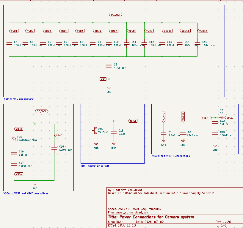
This schematic is based off of the power requirements detailed in the STM32 F405xx/F407xx datasheet and cross-checked with the ST Application Note AN4488 for good measure.
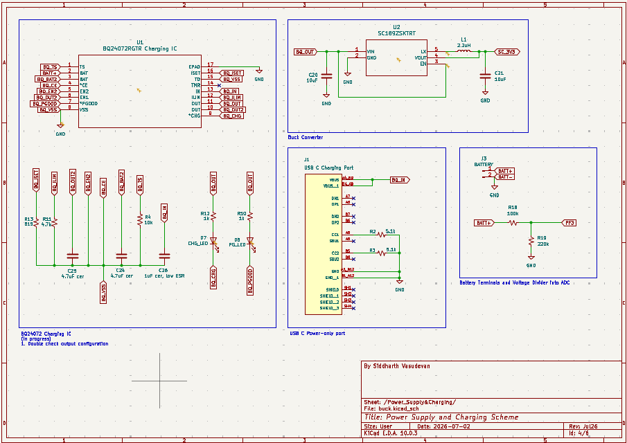
This schematic contains all of the circuitry necessary to make charging possible and exposes pins to the battery. It includes connections for a USB-C socket that serves as the charging port for the camera, connections for the Dynamic Power Path Management IC (charging + power management), the buck converter circuitry to efficiently step down the battery's 3.7V to 3.3V, and the battery terminals, which will use an XH socket. (Initially I planned to have the buck converter on a separate schematic, hence the filename, but there wasn't enough detail to justify a separate schematic)
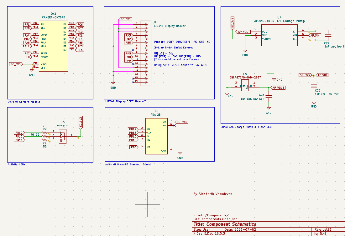
This schematic contains the component connections that provide all the functionality of a camera. It contains the OV7670 Camera Module, the ILI9341 Display header, activity LEDs, and the MicroSD transflash breakout board.
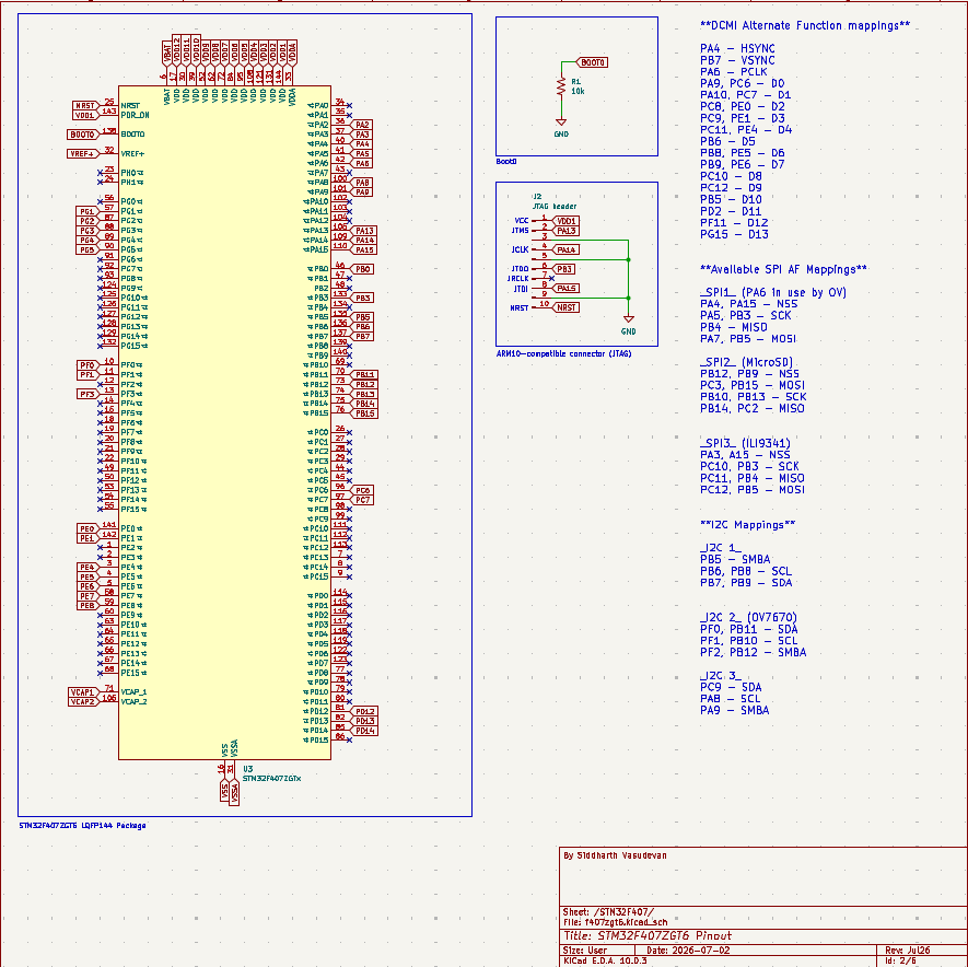
Contains the STM32F407ZGT6 LPQF144 chip. In the near future I will put more circuits in this schematic, such as the bootloader switch.
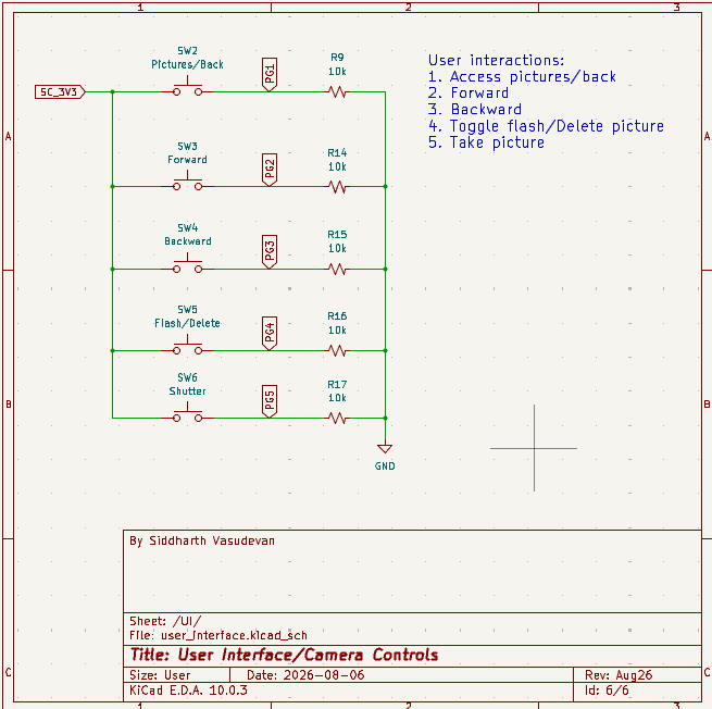
This schematic contains the buttons that will aid the user in communicating with the camera, such as taking pictures, toggling flash, deleting pictures, and navigating saved pictures via a picture menu.
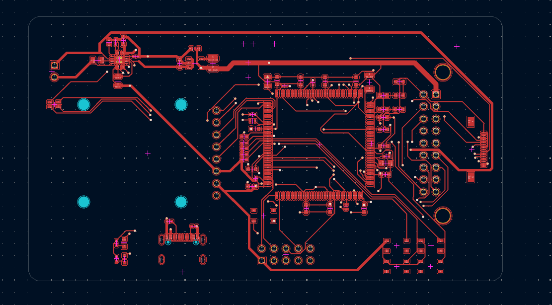
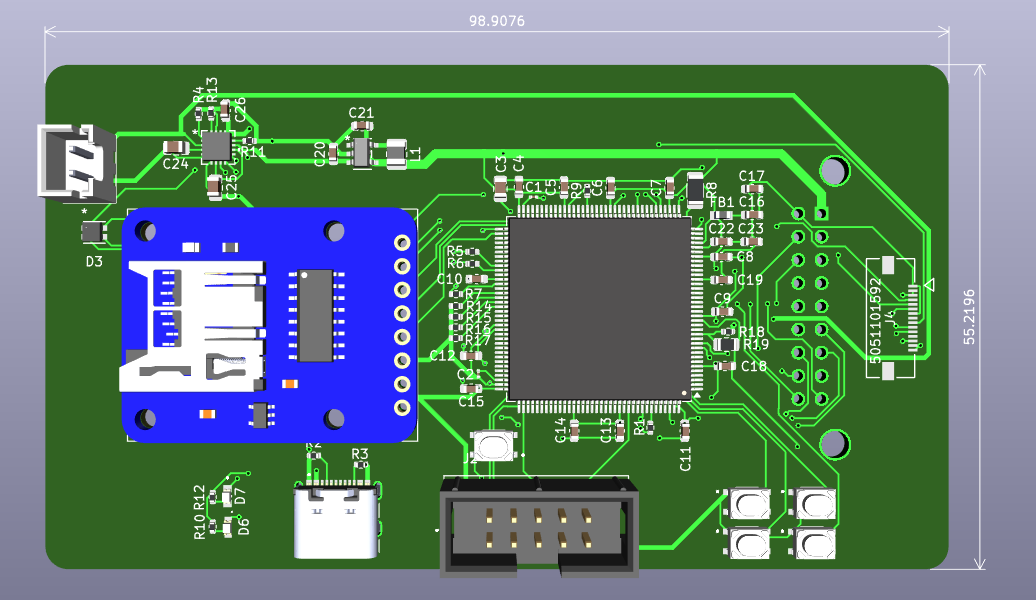
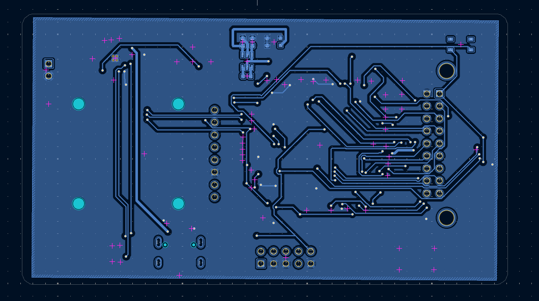
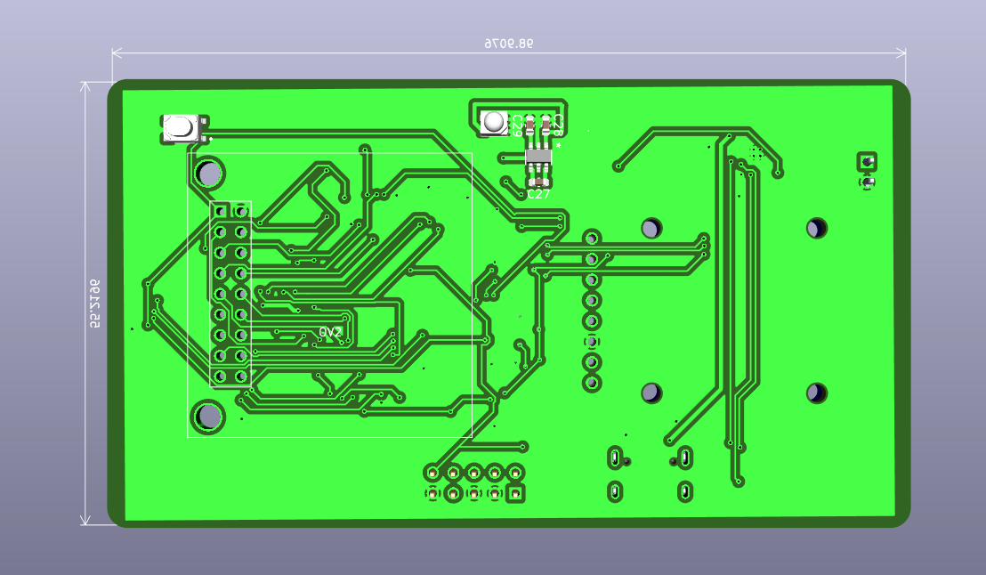
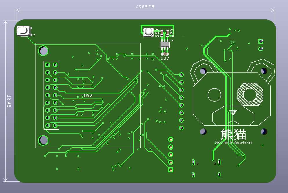
I was recommended to use four layers to separate the ground and VCC Planes better, but this is what I got routing with a two-layer PCB, with the back CU layer housing a ground fill zone. The following layout was verified by the DRC. All dimensions are in mm.
| Layout | 3D Model |
|---|---|
 |  |
| Back Layout | 3D Model |
|---|---|
 |  |
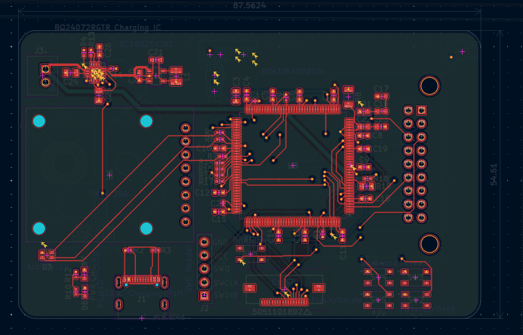
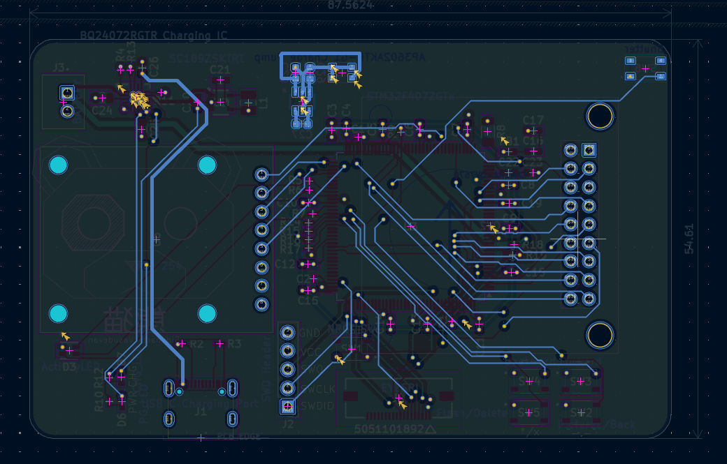
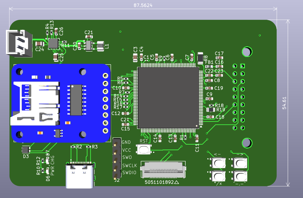
This PCB will be printed once I reverify the schematics and layout. I was able to make the board a little more compact with four layers. The layout was verified by the DRC. All dimensions are in mm.
| Front CU | Back CU |
|---|---|
 |  |
 |  |
| VCC CU | GND CU |
|---|---|
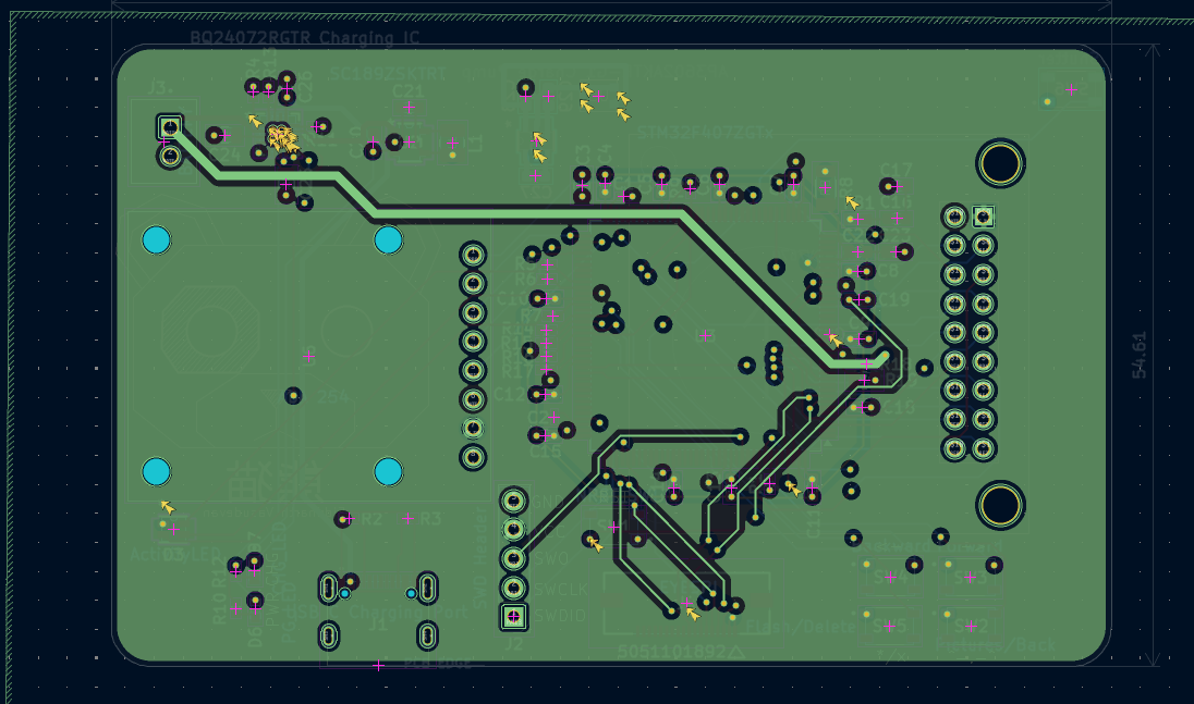 | 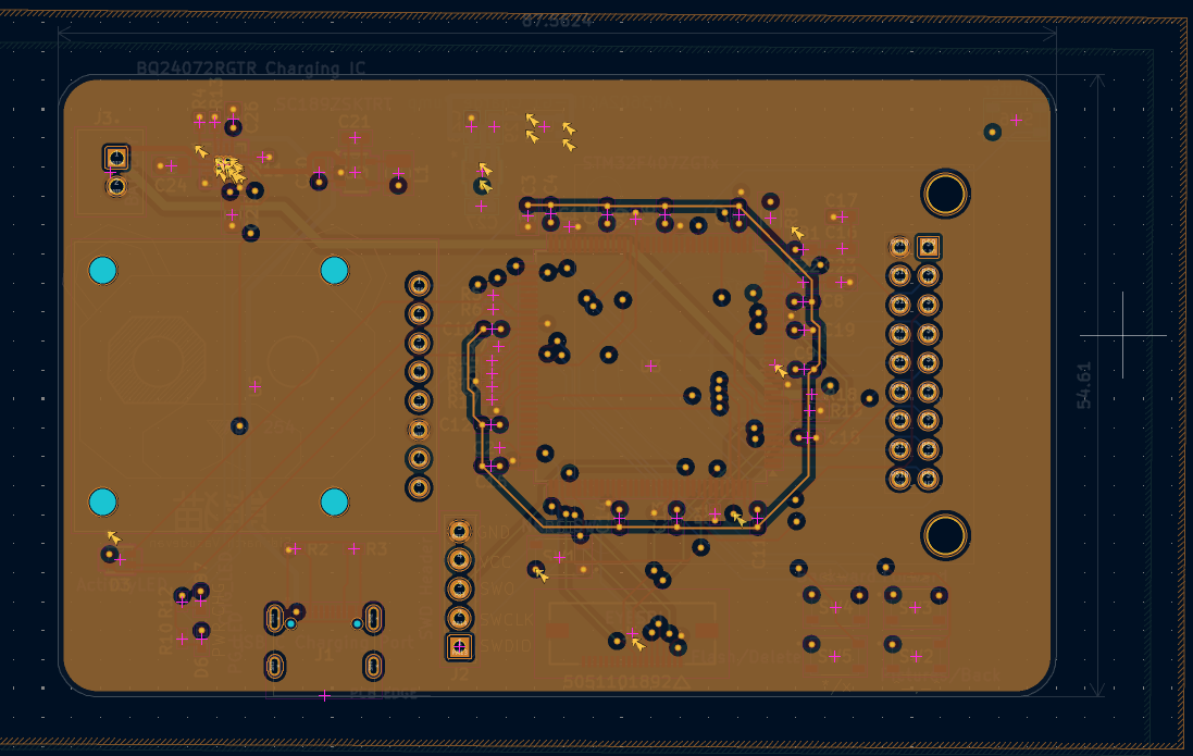 |
| Qty | Value | Footprint | References |
|---|---|---|---|
| 15 | 100nF cer | Capacitor_SMD:C_0603_1608Metric | C4, C5, C6, C7, C8, C9, C10, C11, C12, C13, C14, C15, C17, C18, C23 |
| 7 | 10k | Resistor_SMD:R_0402_1005Metric | R1, R4, R9, R14, R15, R16, R17 |
| 4 | 1uF cer, low ESR | Capacitor_SMD:C_0603_1608Metric | C26, C27, C28, C29 |
| 3 | 4.7uF cer | Capacitor_SMD:C_0805_2012Metric | C3, C24, C25 |
| 2 | 10uF | Capacitor_SMD:C_0603_1608Metric | C20, C21 |
| 2 | 1k | Resistor_SMD:R_0402_1005Metric | R10, R12 |
| 2 | 1uF cer | Capacitor_SMD:C_0603_1608Metric | C16, C22 |
| 2 | 2.2uF cer | Capacitor_SMD:C_0201_0603Metric | C1, C2 |
| 2 | 5.1k | Resistor_SMD:R_0402_1005Metric | R2, R3 |
| 1 | 0.1uF | Capacitor_SMD:C_0603_1608Metric | C19 |
| 1 | 100k | Resistor_SMD:R_0402_1005Metric | R18 |
| 1 | 2.2uH | Inductor_SMD:L_1008_2520Metric | L1 |
| 1 | 22 | Resistor_SMD:R_0402_1005Metric | R5 |
| 1 | 220k | Resistor_SMD:R_0805_2012Metric | R19 |
| 1 | 33 | Resistor_SMD:R_0402_1005Metric | R6 |
| 1 | 4.7k | Resistor_SMD:R_0402_1005Metric | R11 |
| 1 | 47 | Resistor_SMD:R_1206_3216Metric | R8 |
| 1 | 56 | Resistor_SMD:R_0402_1005Metric | R7 |
| 1 | 619 | Resistor_SMD:R_0402_1005Metric | R13 |
| 1 | ADA 254 | 1_MicroSD:MODULE_254 | U6 |
| 1 | AP3602AKTR-G1 Charge Pump | 1_ChargePump:SOT-23-6_DIO | U4 |
| 1 | ActivityLED | 1_LEDs:CLMVC-FKA-CL1D1L71BB7C3C3_CRE | D3 |
| 1 | BATTERY | 1_Headers:JST_B2B-XH-A | J3 |
| 1 | BQ24072RGTR Charging IC | 1_DPPMs:RGT16_1P7X1P7 | U1 |
| 1 | Backward | 1_Switches:SW_SKRPABE010 | SW4 |
| 1 | CAMERA-OV7670 | 1_Cameras:CAMERA-OV7670-DIP | OV2 |
| 1 | CHG_LED | 1_LEDs:LEDC1608X35N_R | D7 |
| 1 | FerriteBead_Small | 1_FerriteBeads:BEADC1608X95N | FB1 |
| 1 | Flash LED | 1_LEDs:QBLP677AD-IWD-2897 | U5 |
| 1 | Flash/Delete | 1_Switches:SW_SKRPABE010 | SW5 |
| 1 | Forward | 1_Switches:SW_SKRPABE010 | SW3 |
| 1 | ILI9341_Display_Header | 1_Headers:CON_5051101592_MOL | J4 |
| 1 | JTAG header | 1_Headers:SULLINS_SBH11-PBPC-D05-ST-BK | J2 |
| 1 | NRST_SW | 1_Switches:SW_SKRPABE010 | SW1 |
| 1 | PG_LED | 1_LEDs:LEDM1608X80_G | D6 |
| 1 | Pictures/Back | 1_Switches:SW_SKRPABE010 | SW2 |
| 1 | SC189ZSKTRT | 1_BuckConverters:SOT23-5-SC189_SEM | U2 |
| 1 | STM32F407ZGTx | Package_QFP:LQFP-144_20x20mm_P0.5mm | U3 |
| 1 | Shutter | 1_Switches:SW_SKRPABE010 | SW6 |
| 1 | USB C Charging Port | 1_Sockets:SAMESKY_UJ20-C-H-G-SMT-1-P16-TR | J1 |
It measures 98.9 × 55.2 mm and has 2 copper layers, 1.6 mm thick.
70 parts, built around the SC189ZSKTRT. The full list of its parts is on this page, with links to each part's symbol and footprint where PCBKit's library has them.
From the lxremipsxm/camera repository on GitHub, at the commit this page was made from: the board is camCAD/camCAD.kicad_pcb and its schematic camCAD/buck.kicad_sch. PCBKit opens the board in the browser, with nothing to install.
Its repository states no licence, so its author keeps all rights: ask lxremipsxm before reusing the design.

SunnyYoshimitsu/CelestiCall
An attempt at making a somewhat modern smartphone with many functions.

JulianVolodia/voltastream0-kicad
KiCad PCB files for high quality audio board with NXP i.MX6ULL processor - ARM Cortex-A7 @ 996MHz; 0.5G/1G RAM; TI PCM5121 or PCM5142 DACs; with RTC

turtlebasket/pocket-operator
HOPE Fa2024 Project: Pocket Operator (portable audio sequencer / synthesizer)


