2 layers116.8 × 30 mm
Type d
google/mozc-devices
Circuit diagrams and firmware source code for Gboard DIY keyboards
14 parts3kApache-2.0
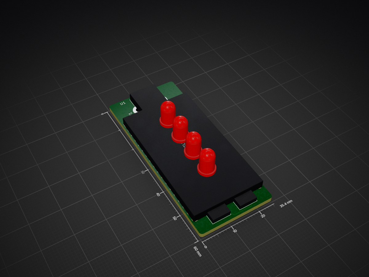
 luytsm/ein-basic-gpio-board
Basic GPIO Board – Embedded Interfacing
Ein basic gpio board is an open-source printed circuit board by luytsm, from the luytsm/ein-basic-gpio-board repository on GitHub. It is a 2-layer board of 25.4 × 60 mm with 14 parts on 34 nets, routed with 56 tracks and 4 vias.
Its parts include 6 resistors, 4 diodes, 2 switches and 1 IC.
Een eenvoudige shield voor de DFRobot FireBeetle 2 ESP32-E (DFR0654). Het bordje brengt een paar basis-I/O-componenten samen, zodat je ze meteen kan gebruiken in de labo-opdrachten van het vak Embedded Interfacing zonder eerst een breadboard op te bouwen.
Op de shield zitten:
| Component | Omschrijving | GPIO | Opmerking |
|---|---|---|---|
| D1 | LED groen | GPIO17 | via R1 naar de anode, katode aan GND |
| D2 | LED geel | GPIO16 | via R2 |
| D3 | LED geel | GPIO4 | via R3 |
| D4 | LED rood | GPIO12 | via R4 |
| SW1 | Drukknop 1 | GPIO13 | schakelt naar +3V3, R5 (10 kΩ) pull-down |
| SW2 | Drukknop 2 | GPIO14 | schakelt naar +3V3, R6 (10 kΩ) pull-down |
| RV1 | Potentiometer (10 kΩ) | GPIO25 | loper op ADC2_CH8, uiteinden op +3V3 en GND |
In test/test.ino staat een testscript waarmee je na het solderen
controleert of alles op het bordje werkt. Open het in de Arduino IDE, kies de
FireBeetle 2 ESP32-E als board en upload het. Open daarna de seriële monitor op
115200 baud.
Het script loopt stap voor stap door alle componenten. Je antwoordt telkens met de drukknoppen: SW1 = OK / verder en SW2 = fout.
Druk nadien op SW1 om de test opnieuw te starten.
| Bestand | Inhoud |
|---|---|
ein-basic-gpio-board.kicad_sch | KiCad-schema |
ein-basic-gpio-board.kicad_pcb | KiCad-PCB-layout |
ein-basic-gpio-board.kicad_pro | KiCad-project |
lib/ | Projectbibliotheek met eigen symbolen en footprints |
sym-lib-table, fp-lib-table | Koppelen lib/ aan het KiCad-project |
test/test.ino | Arduino-testscript |
Het symbool van de FireBeetle 2 en de footprints van de shield en de drukknoppen
zitten in de projectbibliotheek ein-basic-gpio-board in lib/. Je hoeft dus geen
externe bibliotheken toe te voegen: het project opent meteen na het klonen.
| Qty | Value | Footprint | References |
|---|---|---|---|
| 4 | R | Resistor_SMD:R_0805_2012Metric_Pad1.20x1.40mm_HandSolder | R1, R2, R3, R4 |
| 2 | 10k | Resistor_SMD:R_0805_2012Metric_Pad1.20x1.40mm_HandSolder | R5, R6 |
| 2 | GEEL | LED_THT:LED_D5.0mm | D2, D3 |
| 2 | SW_Push | ein-basic-gpio-board:MC_SWITCH_6x6mm_SMD | SW1, SW2 |
| 1 | 10k | Potentiometer_THT:Potentiometer_Bourns_PTV09A-1_Single_Vertical | RV1 |
| 1 | Firebeetle 2 | ein-basic-gpio-board:DFRobot_Firebeetle2_DFR0654_Shield | U1 |
| 1 | GROEN | LED_THT:LED_D5.0mm | D1 |
| 1 | ROOD | LED_THT:LED_D5.0mm | D4 |
It measures 25.4 × 60 mm and has 2 copper layers, 1.6 mm thick.
14 parts. The full list of its parts is on this page, with links to each part's symbol and footprint where PCBKit's library has them.
From the luytsm/ein-basic-gpio-board repository on GitHub, at the commit this page was made from: the board is ein-basic-gpio-board.kicad_pcb and its schematic ein-basic-gpio-board.kicad_sch. PCBKit opens the board in the browser, with nothing to install.
Its repository states no licence, so its author keeps all rights: ask luytsm before reusing the design.
google/mozc-devices
Circuit diagrams and firmware source code for Gboard DIY keyboards


hackclub/OnBoard
💡 Join 1,000 teenagers and make your first PCB with a $100 grant!


Twotoz/C5VRX
Ultra-minimal, zero-CPU 5.8 GHz analog FPV video receiver using ESP32-C5 Wi-Fi 6 PHY MODEM_DIAG, BitScrambler WBFM demodulation & resistor DAC CVBS

