2 layers52.2 × 52.2 mm
Base promicro
google/mozc-devices
Circuit diagrams and firmware source code for Gboard DIY keyboards
30 parts3kApache-2.0

 luisgongod/cabletester12
Arduino 10/16 pin Eurorack IDC Power Cable Tester
Cabletester is an open-source printed circuit board by luisgongod, from the luisgongod/cabletester repository on GitHub. It is a 2-layer board of 132.5 × 50.5 mm with 30 parts on 45 nets, routed with 150 tracks and 0 vias.
Its parts include 17 resistors, 6 connectors, 1 capacitor and 1 IC. It belongs with the audio and music boards and the AVR (ATmega, ATtiny) boards of this library.
Forked from holmesrichards Original idea and testing algorithm goes to tomarus. This version has a new PCB and Some modifications to the FW made into a Platformio project.
GND-VCC-SCL-SDA and VCC-GND-SCL-SDA Oled configuration allowed.The original documentation and repo information is under OGs folder. Gerbers, schematics and BOM are under HW while the Platformio project is under FW.
Default values should work fine:
const int expect[] = {746, 544, 395, 286, 204, 130, 80, 35};But is recommended to make a calibration run to change to proper values. To do that:
DEBUG mode by uncommenting line 7.expect values will be printed, they should not differ too much from default values.expect values, comment the DEBUG define and re-flash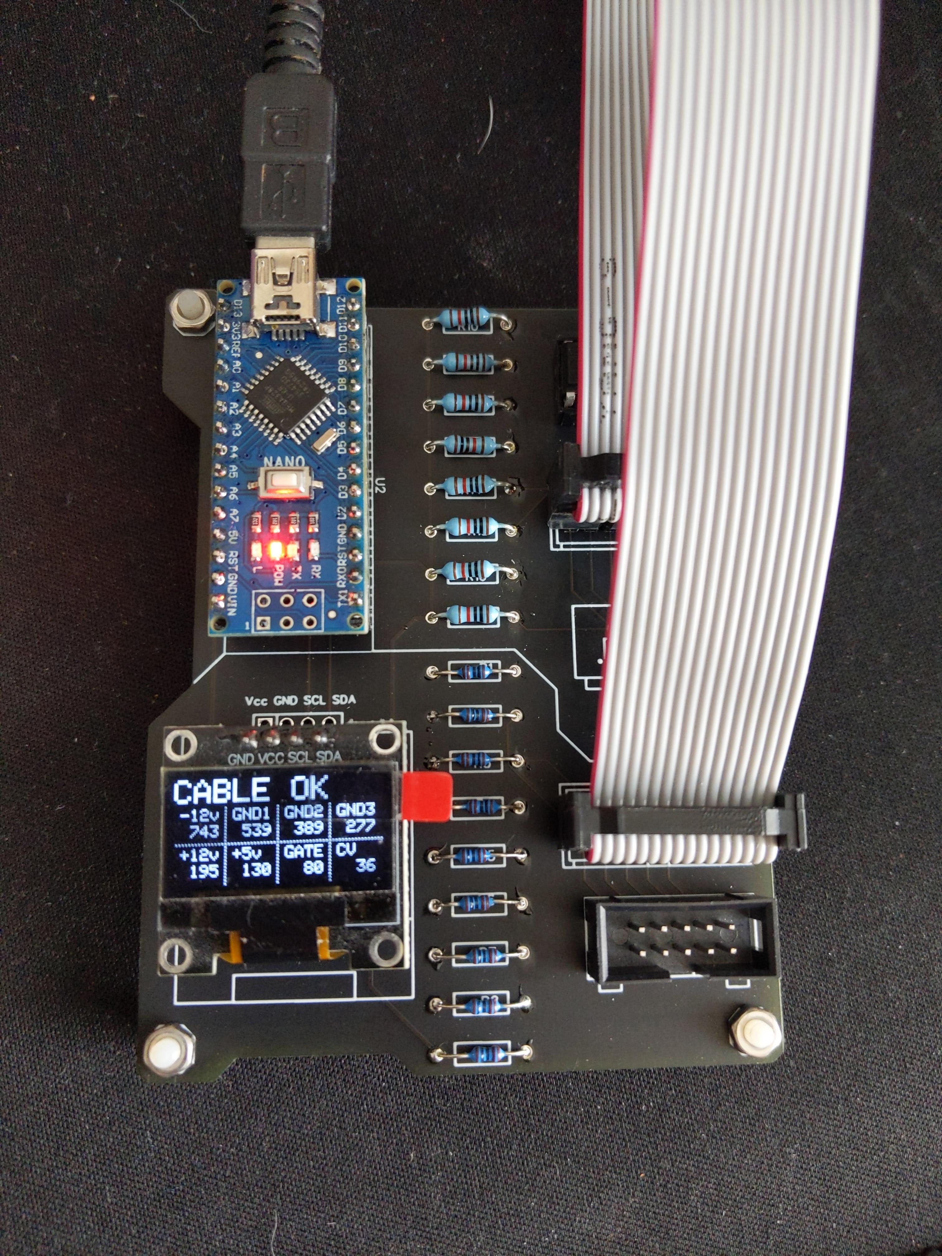
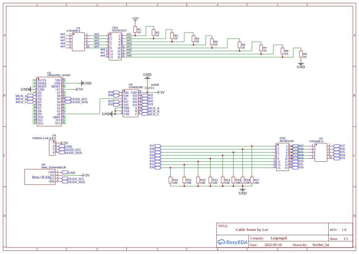
| Qty | Value | Footprint | References |
|---|---|---|---|
| 9 | 1K | ao_tht:R_Axial_DIN0207_L6.3mm_D2.5mm_P7.62mm_Horizontal | R1, R2, R3, R4, R5, R6, R7, R8, R9 |
| 8 | 10K | ao_tht:R_Axial_DIN0207_L6.3mm_D2.5mm_P7.62mm_Horizontal | R10, R11, R12, R13, R14, R15, R16, R17 |
| 2 | 4 pin header | Connector_PinSocket_2.54mm:PinSocket_1x04_P2.54mm_Vertical | J5, J6 |
| 2 | IDC 2x5 | ao_tht:Power_Header | J1, J3 |
| 2 | IDC 2x8 | Connector_IDC:IDC-Header_2x08_P2.54mm_Vertical | J2, J4 |
| 1 | 100n | ao_tht:C_Disc_D3.0mm_W1.6mm_P2.50mm | C1 |
| 1 | 4051 | ao_tht:DIP-16_W7.62mm_Socket_LongPads | U1 |
| 1 | Arduino_Nano_v3.x | ao_tht:Arduino_Nano | A1 |
The 26 most common of 30 parts.
google/mozc-devices
Circuit diagrams and firmware source code for Gboard DIY keyboards


VoronDesign/Voron-Hardware
Cool Hardware designed by the Voron Design group

hoglet67/RGBtoHDMI
Bare-metal Raspberry Pi project that provides pixel-perfect sampling of Retro Computer RGB/YUV video and conversion to HDMI

tenderlove/initial-v
It's a BMW shifter converted to a Bluetooth Keyboard that you use with Vim

hackclub/OnBoard
💡 Join 1,000 teenagers and make your first PCB with a $100 grant!


It measures 132.5 × 50.5 mm and has 2 copper layers, 1.6 mm thick.
30 parts. The full list of its parts is on this page, with links to each part's symbol and footprint where PCBKit's library has them.
From the luisgongod/cabletester repository on GitHub, at the commit this page was made from: the board is OGs/cabletester/cabletester.kicad_pcb. PCBKit opens the board in the browser, with nothing to install.
Its repository states no licence, so its author keeps all rights: ask luisgongod before reusing the design.