2 layers82.7 × 95.8 mm

 lowj/tp-keyboard52
Keyboard from thinkpad laptop
Tp pcb is an open-source printed circuit board by lowj, from the lowj/tp-keyboard repository on GitHub. It is a 2-layer board of 90.5 × 97.3 mm with 17 parts on 54 nets, routed with 274 tracks and 26 vias.
Its parts include 4 resistors, 4 connectors, 1 capacitor, 1 IC and 1 diode. It belongs with the keyboards and input boards and the AVR (ATmega, ATtiny) boards of this library.
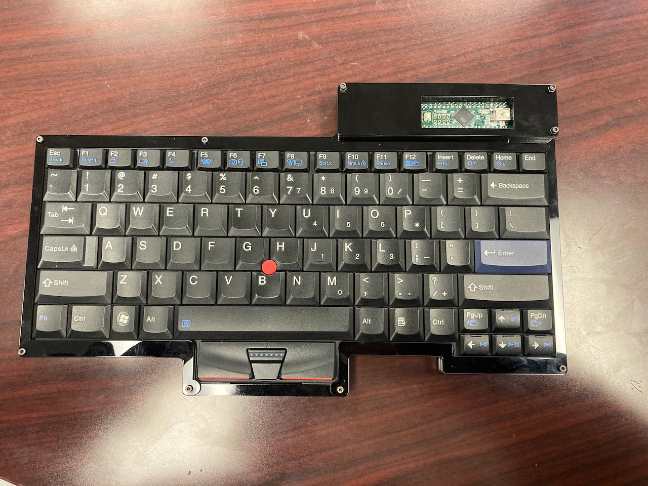
The goal of this project is to make a useable desktop keyboard from the keyboard of the ThinkPad L420. It uses a custom PCB to connect to the FFC cables of the keyboard matrix and trackpoint module to a Teensy++ board.
The Teensy++ runs QMK firmware to scan the keyboard matrix and read the signals from the trackpoint module. QMK has a PS/2 library which is used to make the trackpoint module functional.
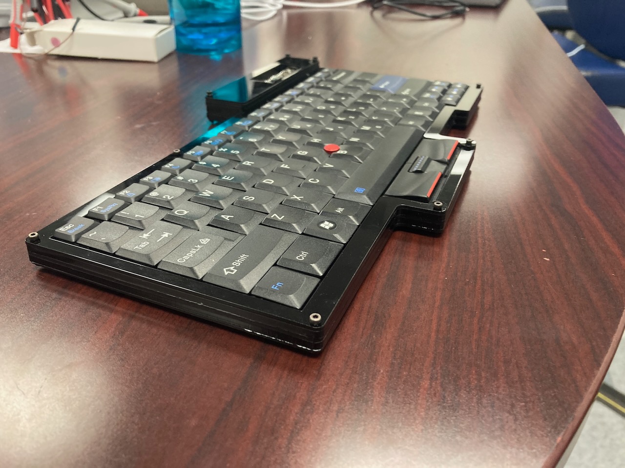
The trackpoint module has an 8 pin FFC cable.
The modules clock pin needs to connect to PD2 and data pin needs to connect to PD5 of the teensy

The keyboard has a 30 pin FFC cable connected to it. These are the rows and column pins for the matrix

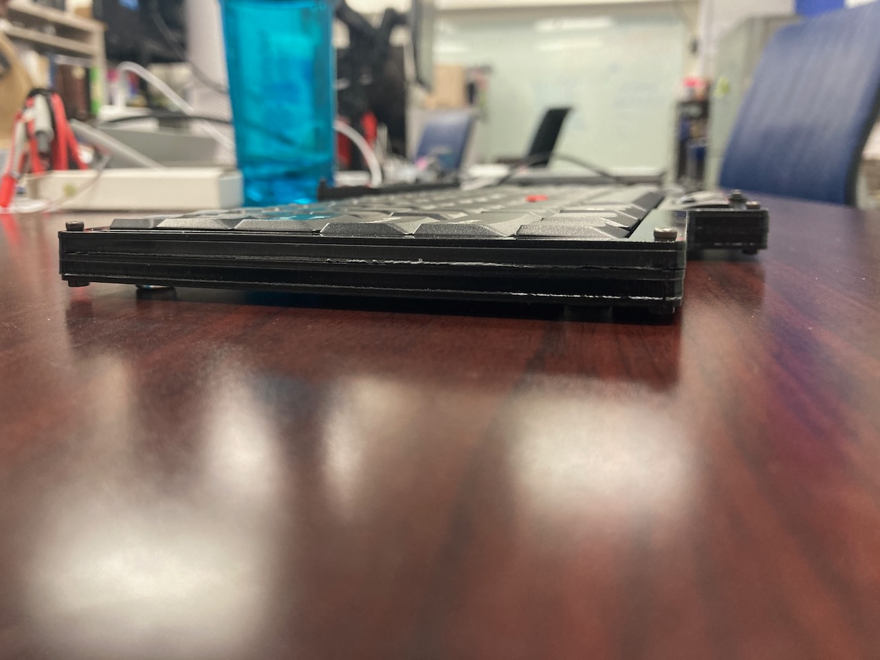
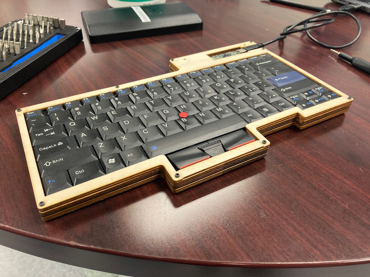
The housing is comprised of laser cut wood/acrylic sheets (1.5mm and 3mm) and M2 screws.
This is the stackup I used. However thicknesses can be varied to make the keyboard lower or higher profile.
[      shield_2.dxf (1.5mm)      ]
[      shield_1.dxf (1.5mm)      ]
[      shield_1.dxf (3.0mm)      ]
[       layer4.dxf (1.5mm)       ]
[  layer3 cover ffc.dxf (3.0mm)  ]
[       layer2.dxf (3.0mm)       ]
[    layer2_nousb.dxf (1.5mm)    ]
[       layer1.dxf (1.5mm)       ]
Some notes about the housing:
layer2_nousb.dxf has no usb cutout while laye2.dxf has a cut out for usb. These allow for adjusting when the usb cut-out starts.layer3 cover ffc.dxf's thickness should try to match the height of the edge of the keyboard matrix module. This is because the keyboard module lays ontop of layer2 and layer3 cover ffc goes along the edges of the keyboard module. layer4 goes ontop and helps secure/hold down the keyboard module. If the layer3 section is too thick, then the edges of the keyboard module wont be secured leading to more wobble. If the layer3 section is too thin, the keyboard will be held down, but layer4 would not be able to sit flush. If layer 3 is the right height then there would be some pressure holding the keyboard down and layer4 would sit flush.layer4.dxf is better if it is thinner (1.5mm) so fingers dont hit it when using keys on the edgeslayer1.dxf [WIP] there is a hole in the middle to secure the keyboard down, it goes into the screwhole in the back of the keyboard module, this helps with wobble when using the trackpointOther than these notes, the thicknesses of each layer can be adjusted.
 This is the dev board I created and used to decode the matrix of the keyboard.

| Qty | Value | Footprint | References |
|---|---|---|---|
| 2 | 4.7k | Resistor_SMD:R_1206_3216Metric_Pad1.42x1.75mm_HandSolder | R1, R2 |
| 1 | 100K | Resistor_SMD:R_1206_3216Metric_Pad1.42x1.75mm_HandSolder | R4 |
| 1 | 2.2uF | Capacitor_SMD:C_1206_3216Metric_Pad1.42x1.75mm_HandSolder | C1 |
| 1 | 30 Pin FFC | custom:FFC_30_GCT | J3 |
| 1 | Conn_01x08_Male | custom:FFC_8_TE | J4 |
| 1 | LED | LED_SMD:LED_1206_3216Metric_Pad1.42x1.75mm_HandSolder | D1 |
| 1 | R | Resistor_SMD:R_1206_3216Metric_Pad1.42x1.75mm_HandSolder | R3 |
| 1 | RGB LEDs | Connector_PinHeader_2.54mm:PinHeader_1x03_P2.54mm_Vertical | J2 |
| 1 | Teensy++2.0 | teensy:Teensy2.0++ | U1 |
| 1 | Trackpoint | Connector_PinHeader_2.54mm:PinHeader_1x04_P2.54mm_Vertical | J1 |
The 11 most common of 17 parts.


hoglet67/RGBtoHDMI
Bare-metal Raspberry Pi project that provides pixel-perfect sampling of Retro Computer RGB/YUV video and conversion to HDMI


hackclub/OnBoard
💡 Join 1,000 teenagers and make your first PCB with a $100 grant!

DDeGonge/OS-ARM
This arm is not industrial and it will not be fast, but that is not my goal. But it will hopefully be a very nice looking arm fully capable of 6dof motion, cheap enough to keep it accessable but capable enough to…


It measures 90.5 × 97.3 mm and has 2 copper layers, 1.6 mm thick.
17 parts. The full list of its parts is on this page, with links to each part's symbol and footprint where PCBKit's library has them.
From the lowj/tp-keyboard repository on GitHub, at the commit this page was made from: the board is pcbs/tp_pcb/board/board.kicad_pcb. PCBKit opens the board in the browser, with nothing to install.
Its repository states no licence, so its author keeps all rights: ask lowj before reusing the design.