2 layers144 × 79 mm
MacroPad
loredavid/Hapticpad
A 6 button macropad with a display for button labels and a mouse knob with haptic feedback! — v2 redesign: new Pico SDK firmware + USB configurator.
59 parts1CERN-OHL-S-2.0

 loredavid/Hapticpad1
A 6 button macropad with a display for button labels and a mouse knob with haptic feedback! — v2 redesign: new Pico SDK firmware + USB configurator.
MacroPad Controller Board is an open-source printed circuit board by loredavid, from the loredavid/Hapticpad repository on GitHub, published under the CERN-OHL-S-2.0 licence. It is a 2-layer board of 70 × 50.5 mm with 29 parts on 40 nets, routed with 204 tracks and 86 vias.
Its parts include 1 capacitor, 1 IC and 1 connector. It belongs with the keyboards and input and robots and motor control boards and the RP2040 boards of this library.
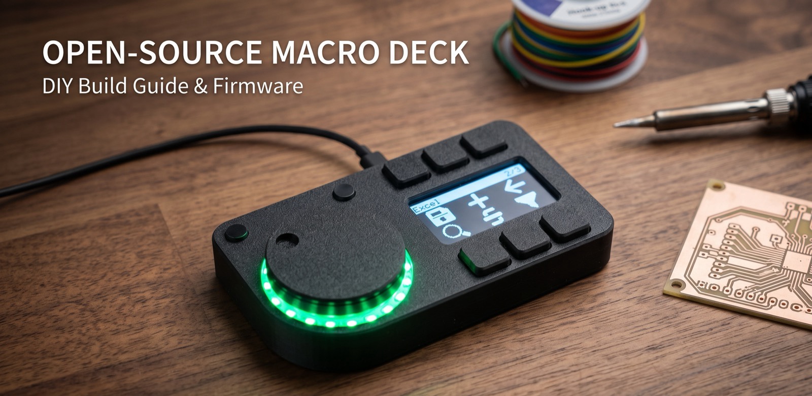
A six-key macropad with an OLED label screen and a brushless wheel that generates its detents in software — the clicks you feel are torque curves, not a mechanical ratchet, so every profile can have a different feel.
Version 2 is a ground-up firmware rewrite on the Raspberry Pi Pico SDK, plus a desktop configurator that sets up the whole device over the USB cable. The hardware is unchanged from the original project by dmcke5 — the same two PCBs and the same printed parts run this firmware without any rewiring.
| v1 (Arduino) | v2 (Pico SDK) | |
|---|---|---|
| Macro delivery | sendKeystroke() called from both cores; reports lost | one core owns USB; queued, never dropped silently |
| Macro delays | delay() froze screen, LEDs and buttons | non-blocking playback, UI keeps running |
| Wheel zoom | broken (Ctrl written into the modifier byte as a keycode) | works, and is one preset among twelve |
| Display | bit-banged SPI, ~30 ms of blocked CPU per frame | PIO + DMA, ~1 ms, CPU free |
| LED ring | FastLED bit-bang with interrupts off | PIO + DMA |
| Encoder | 2 GPIO interrupts, up to 80 k/s | PIO decoder, zero interrupts |
| Macro steps | 3 per button | 8 per button |
| Config | XML on the card, edited by hand | on-device menu, USB configurator, or plain-text files |
| Firmware update | BOOTSEL button | menu entry or a button in the configurator |
| Icons | every .bin on the original card was 72 bytes of zeros | converter that verifies its own output |
Full details in CHANGELOG.md; coming from a working v1 pad, read docs/migration-from-v1.md first.
off free clicky ratchet damped 4points) and 12
function presets (scroll, zoom, volume, tabs, history, undo/redo, timeline…)off solid rainbow breath bands halo reactive profilefirmware/ HapticPad 2.0 firmware — C/C++ on the Pico SDK
release/ hapticpad-2.0.0.uf2, ready to flash
configurator/ desktop app: profiles, macros, icons, settings over USB
hardware/ PCBs (KiCad + gerbers), 3D printable and machinable parts, BOM
sd-card/ a starter card: config.txt, example profiles, icons
assets/ 190+ PNG icons to import with the configurator
docs/ everything below1. Flash the firmware. Hold BOOTSEL while plugging the pad in, then drag
firmware/release/hapticpad-2.0.0.uf2 onto the RPI-RP2 drive. That is the
last time you need the BOOTSEL button — afterwards the pad's menu and the
configurator can both reboot it into the bootloader.
2. Prepare the card. Copy the contents of sd-card/ onto a FAT32 microSD
and insert it. See docs/sd-card.md.
3. Run the configurator.
python3 configurator/hapticpad.pyNo installation: it runs on the Python that ships with macOS and opens in your browser. See configurator/README.md.
Building the firmware yourself is in firmware/README.md.
| Document | What it covers |
|---|---|
| docs/hardware.md | BOM, PCB assembly, motor stack, wiring |
| docs/sd-card.md | card layout, what the firmware writes |
| docs/profile-format.md | profile keys, wheel modes, action vocabulary |
| docs/configuration.md | device settings, and how profiles override them |
| docs/serial-protocol.md | the USB command set |
| docs/architecture.md | how the two cores divide the work |
| docs/migration-from-v1.md | upgrading a v1 pad |
| docs/troubleshooting.md | when something does not work |
| firmware/README.md | building, flashing, debugging |
| configurator/README.md | the desktop app |
The hardware, the enclosure and the original v1 firmware are the work of dmcke5 — Hapticpad, project video. Version 2 is a firmware and software rewrite on top of that hardware.
Licensed under the CERN Open Hardware Licence v2 — Strongly Reciprocal, the same licence as the original project. See LICENSE.
| Qty | Value | Footprint | References |
|---|---|---|---|
| 3 | GND | TestPoint:TestPoint_THTPad_D1.0mm_Drill0.5mm | TP1, TP5, TP25 |
| 2 | VCC | TestPoint:TestPoint_THTPad_D1.0mm_Drill0.5mm | TP4, TP24 |
| 1 | +5V | TestPoint:TestPoint_THTPad_D1.0mm_Drill0.5mm | TP2 |
| 1 | 1 | Parts:Sparkfun_TMC6300 | U1 |
| 1 | 1 | Parts:RP2040PLUS_SMD | Waveshare_RP2040PLUS |
| 1 | 10000pF 50V | Capacitor_SMD:C_0603_1608Metric_Pad1.08x0.95mm_HandSolder | C1 |
| 1 | A | TestPoint:TestPoint_THTPad_D1.0mm_Drill0.5mm | TP22 |
| 1 | B | TestPoint:TestPoint_THTPad_D1.0mm_Drill0.5mm | TP23 |
| 1 | BTN_1 | TestPoint:TestPoint_THTPad_D1.0mm_Drill0.5mm | TP12 |
| 1 | BTN_2 | TestPoint:TestPoint_THTPad_D1.0mm_Drill0.5mm | TP11 |
| 1 | Conn_01x06_Pin | Connector_PinHeader_2.54mm:PinHeader_1x06_P2.54mm_Vertical | J1 |
| 1 | D_CLK | TestPoint:TestPoint_THTPad_D1.0mm_Drill0.5mm | TP7 |
| 1 | D_CS | TestPoint:TestPoint_THTPad_D1.0mm_Drill0.5mm | TP8 |
| 1 | D_DC | TestPoint:TestPoint_THTPad_D1.0mm_Drill0.5mm | TP9 |
| 1 | D_DIN | TestPoint:TestPoint_THTPad_D1.0mm_Drill0.5mm | TP6 |
| 1 | D_RST | TestPoint:TestPoint_THTPad_D1.0mm_Drill0.5mm | TP10 |
| 1 | LED | TestPoint:TestPoint_THTPad_D1.0mm_Drill0.5mm | TP3 |
| 1 | S1 | TestPoint:TestPoint_THTPad_D1.0mm_Drill0.5mm | TP13 |
| 1 | S2 | TestPoint:TestPoint_THTPad_D1.0mm_Drill0.5mm | TP14 |
| 1 | S3 | TestPoint:TestPoint_THTPad_D1.0mm_Drill0.5mm | TP15 |
| 1 | S4 | TestPoint:TestPoint_THTPad_D1.0mm_Drill0.5mm | TP16 |
| 1 | S5 | TestPoint:TestPoint_THTPad_D1.0mm_Drill0.5mm | TP17 |
| 1 | S6 | TestPoint:TestPoint_THTPad_D1.0mm_Drill0.5mm | TP18 |
| 1 | U | TestPoint:TestPoint_THTPad_D2.0mm_Drill1.0mm | TP19 |
| 1 | V | TestPoint:TestPoint_THTPad_D2.0mm_Drill1.0mm | TP20 |
| 1 | W | TestPoint:TestPoint_THTPad_D2.0mm_Drill1.0mm | TP21 |
It measures 70 × 50.5 mm and has 2 copper layers, 1.6 mm thick.
29 parts. The full list of its parts is on this page, with links to each part's symbol and footprint where PCBKit's library has them.
From the loredavid/Hapticpad repository on GitHub, at the commit this page was made from: the board is hardware/pcb/MacroPad Controller Board/MacroPad Controller Board.kicad_pcb and its schematic hardware/pcb/MacroPad Controller Board/MacroPad Controller Board.kicad_sch. PCBKit opens the board in the browser, with nothing to install.
Its repository publishes it under the CERN-OHL-S-2.0 licence: you may reuse it on that licence's terms (keep the author's notice, and for a copyleft licence share your changes alike).
loredavid/Hapticpad
A 6 button macropad with a display for button labels and a mouse knob with haptic feedback! — v2 redesign: new Pico SDK firmware + USB configurator.

gusmanb/logicanalyzer
24 channel, 100Msps logic analyzer hardware and software

VoronDesign/Voron-Hardware
Cool Hardware designed by the Voron Design group

hoglet67/RGBtoHDMI
Bare-metal Raspberry Pi project that provides pixel-perfect sampling of Retro Computer RGB/YUV video and conversion to HDMI

hackclub/OnBoard
💡 Join 1,000 teenagers and make your first PCB with a $100 grant!

OLIMEX/DIY-LAPTOP
Do It Yourself Open Source Hardware and Software Modular Hacker's Friendly Laptop

UtilitechAS/amsreader-firmware
ESP8266 and ESP32 compatible firmware to read, interpret and publish data to MQTT from smart electrical meters, both DLMS and DSMR is supported

