
2 layers35 × 12.4 mm
Rdio filter uhf
loopmasta/rdio
A VHF/UHF radio you control from your iPhone: ESP32 + DRA818/SA818 over Wi-Fi. Hardware design and screenshots.
9 parts
 loopmasta/rdio
A VHF/UHF radio you control from your iPhone: ESP32 + DRA818/SA818 over Wi-Fi. Hardware design and screenshots.
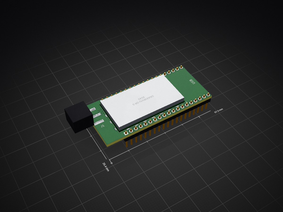
Rdio is an open-source printed circuit board by loopmasta, from the loopmasta/rdio repository on GitHub. It is a 2-layer board of 57.3 × 25.4 mm with 14 parts on 16 nets, routed with 183 tracks and 21 vias.
It is built around the CONSMA020.062-G. Its parts include 5 capacitors, 4 resistors, 3 connectors and 1 IC. It belongs with the radio and wireless boards and the ESP32 boards of this library.
A VHF/UHF radio you control from your iPhone. An ESP32 drives a DRA818 / SA818 transceiver module and streams the audio over Wi-Fi to a native iOS app: listen, push-to-talk, keep a list of channels and repeaters, and read APRS packets in a chat view.
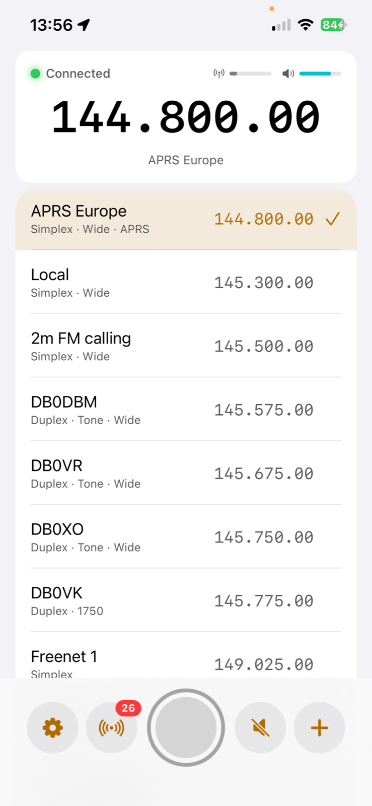 | 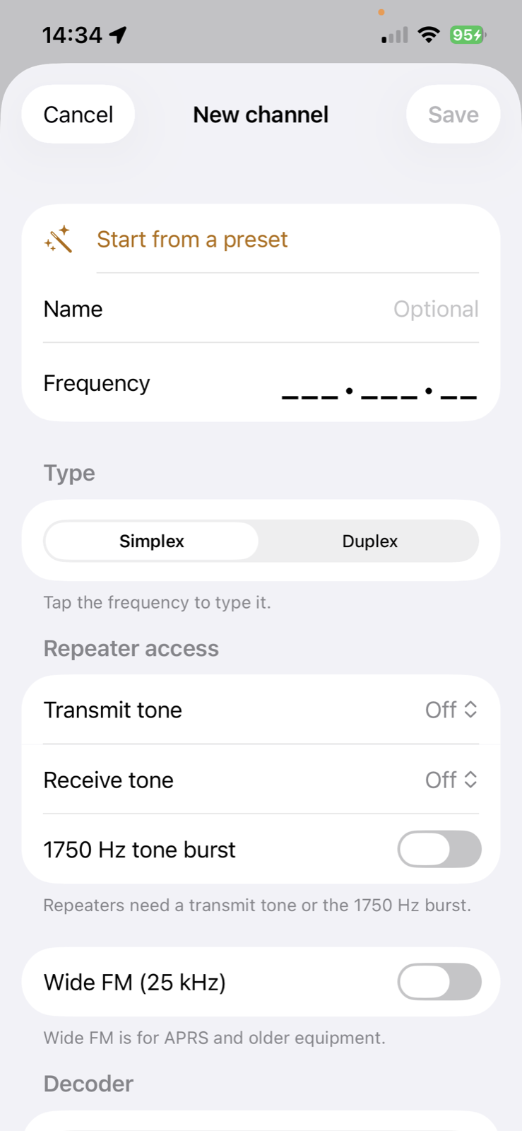 | 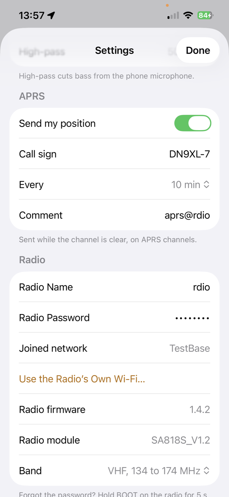 | 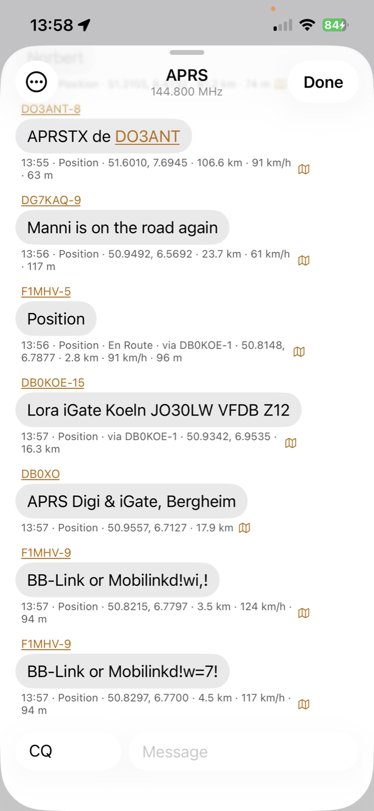 |
| Main screen | Channel editor | Settings | APRS chat |
_rdio._tcp, with its name, module type and firmware version). The app lists the radios it finds in Settings → Radio and switches between them with one tap. Give every radio its own name (Settings → Radio Name), because the name is also its Wi-Fi and host name.Working on a real radio: receive, transmit, channel handling, tones, tone burst, APRS decoding, and the APRS position beacon (tested over the air).
Not done yet: a scan function and a TX power switch (the carrier board wires the module's high/low power pin, but the firmware does not use it yet).
The carrier board and the harmonic filters below are designed but not built or measured yet. The filters are simulated only; check them with a NanoVNA before relying on them.
Everything is KiCad 10 and is generated by scripts, so the boards can be rebuilt and changed in code.
A 57.3 × 25.4 mm two-layer board for an ESP32 38-pin DevKit (NodeMCU-32S style) and a DRA818 / SA818 module. The DevKit's own pins are soldered into the board from below, the radio module sits on the top side, and an SMA jack on the end opposite the DevKit's USB port carries the antenna signal on a short track.
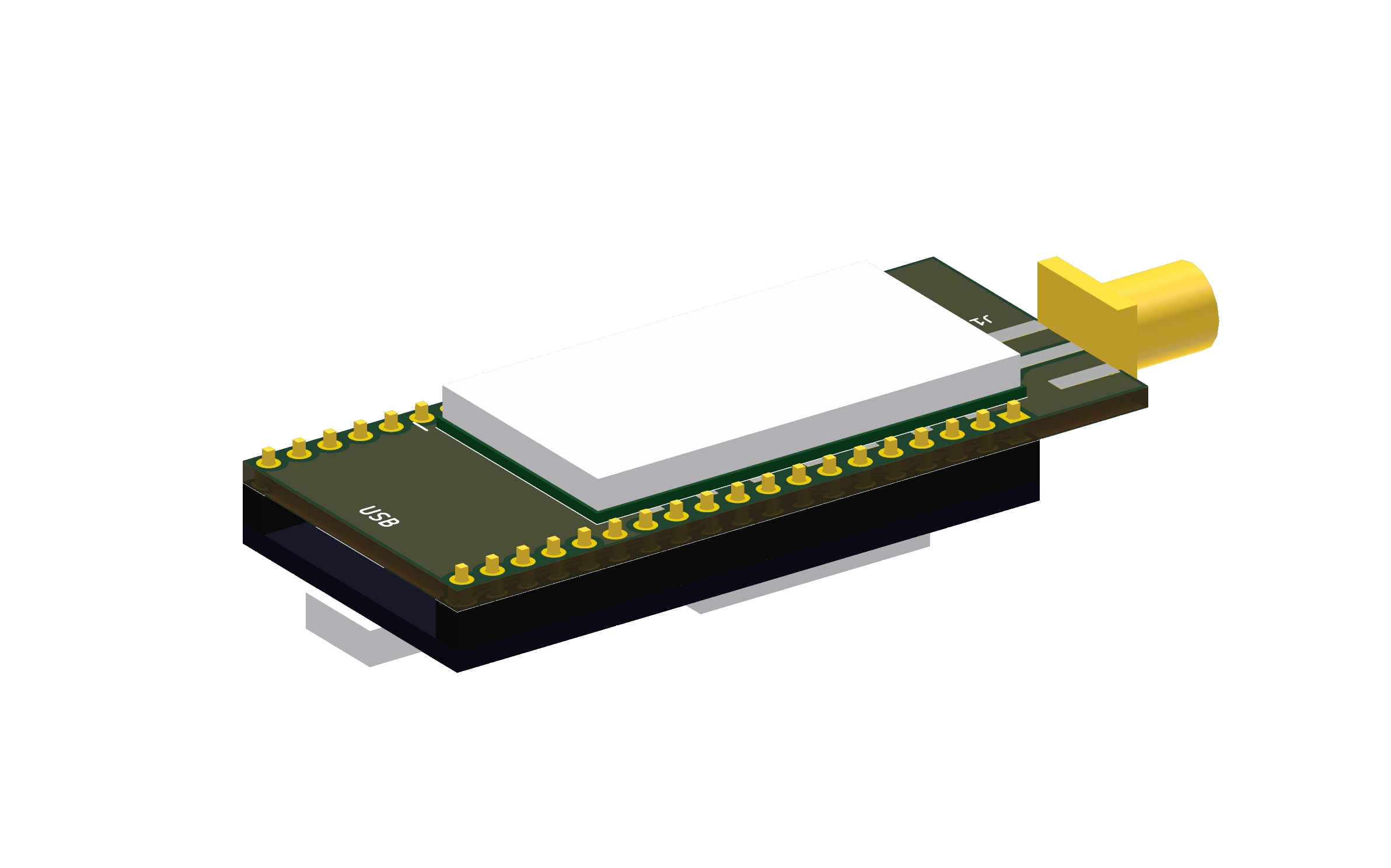 | 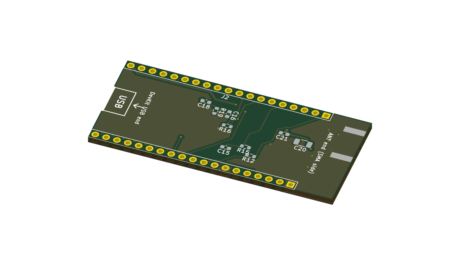 |
| Top: radio module, DevKit below, SMA jack | Bottom: audio and supply parts, DevKit pin rows |
| Function | ESP32 pin |
|---|---|
| Module UART (RX / TX) | GPIO16 / GPIO17 |
| Power down (high = on) | GPIO19 |
| PTT (low = transmit) | GPIO18 |
| Squelch in | GPIO32 |
| RX audio in (ADC) | GPIO34, biased to 1.75 V by GPIO26 |
| TX audio out | GPIO25 |
| High / low power | GPIO23 (floating = 1 W, low = 0.5 W; not used by the firmware yet) |
Two small all-SMD low-pass filters (7th-order Chebyshev, 0.1 dB ripple, 50 Ω) that go between the board's SMA jack and the antenna and cut the radio module's harmonics. Details, simulation and parts notes: hardware/filter/README.md.
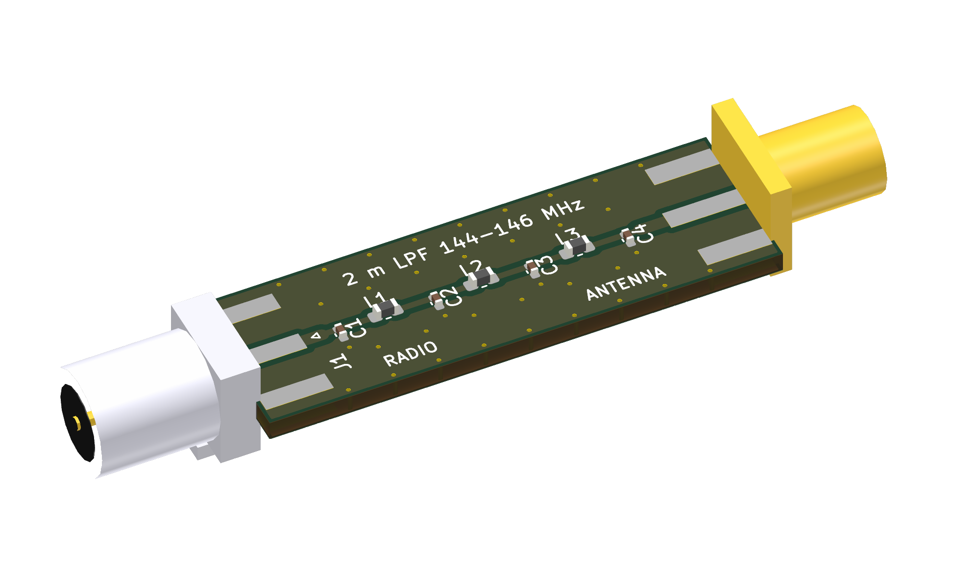 | 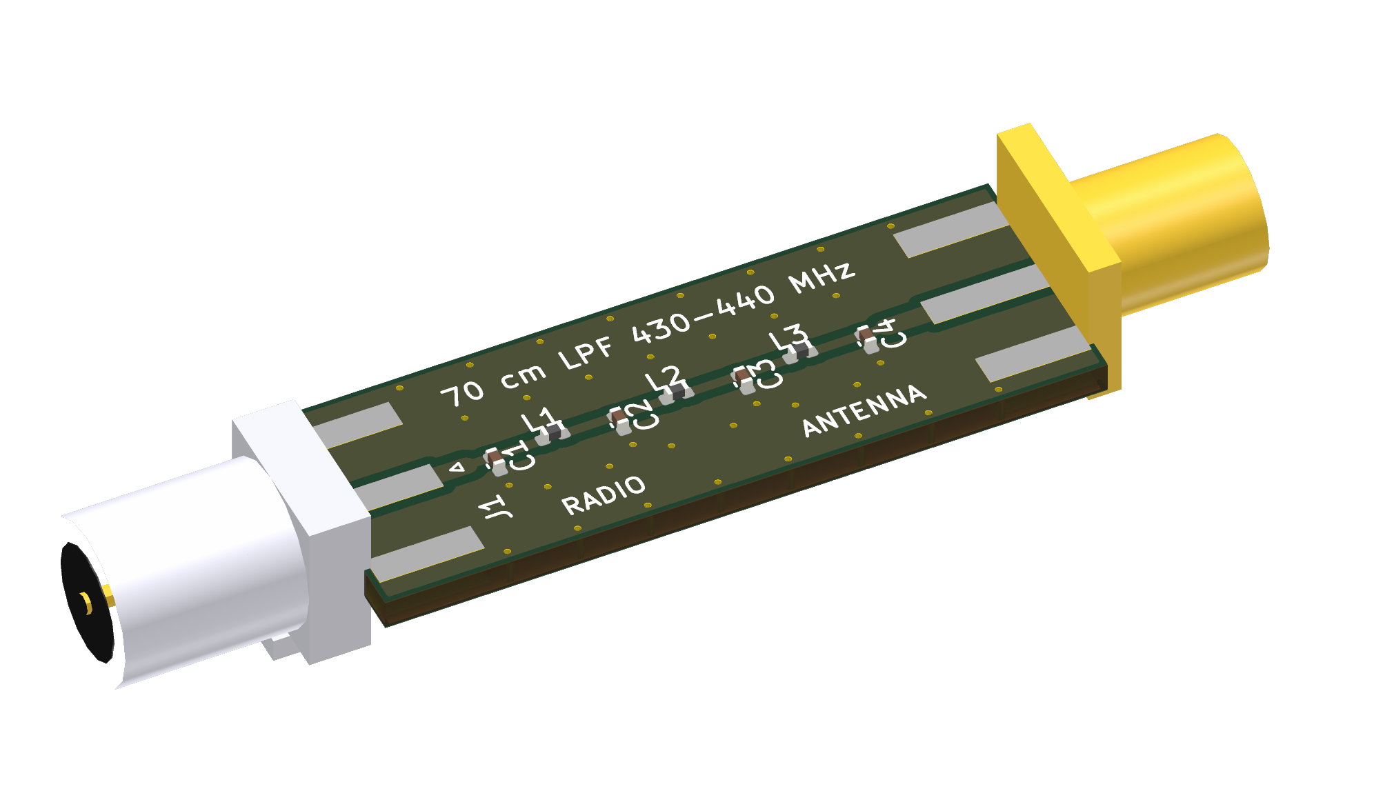 |
| 2 m, 144–146 MHz | 70 cm, 430–440 MHz |
| 2 m | 70 cm | |
|---|---|---|
| Passband | 144–146 MHz | 430–440 MHz |
| Insertion loss (simulated) | 0.56 dB | 0.50 dB |
| 2nd harmonic (simulated) | 52 dB down | 63 dB down |
| Board size | 38.0 × 12.4 mm | 34.4 × 12.4 mm |
Gerber, drill, bill of materials and placement files for JLCPCB are in hardware/jlcpcb/: radio/ for the carrier board and filters/vhf, filters/uhf for the filters. Check the LCSC part numbers in the bills of materials against JLCPCB's parts library before you order. The SMA connectors, the DevKit headers and the radio module are soldered by hand.
Transmitting needs an amateur radio licence and must follow the rules that apply to you. The app limits the transmit frequency to the selected band, but you are responsible for staying within your licence and the local regulations.
Privacy: the app has no accounts, analytics or tracking. See the privacy policy.
This repository lets a small group of testers order the hardware, build it, flash the firmware and install the app, with no software knowledge or development tools. It holds the hardware design (hardware/), the screenshots (docs/) and this description.
The software is not included and does not need to be built:
The app will be linked here once it is available. The software might become open source at some point.
| Qty | Value | Footprint | References |
|---|---|---|---|
| 2 | 100nF | C_0603_1608Metric | C18, C21 |
| 2 | 10k | R_0603_1608Metric | R12, R15 |
| 1 | ESP32_DevKit_38pin | DK1 | |
| 1 | 1uF | C_0603_1608Metric | C15 |
| 1 | 220R | R_0603_1608Metric | R19 |
| 1 | 220nF | C_0603_1608Metric | C16 |
| 1 | 22k | R_0603_1608Metric | R16 |
| 1 | 47uF | C_1206_3216Metric | C20 |
| 1 | CONSMA020.062-G | CONSMA020_062_G | J1 |
| 1 | DRA818V/U or SA818-V/U | DRA818_SA818 | U6 |
| 1 | ESP32 DevKit, row J2 | PinHoles_1x19_P2.54mm | J2 |
| 1 | ESP32 DevKit, row J3 | PinHoles_1x19_P2.54mm | J3 |
It measures 57.3 × 25.4 mm and has 2 copper layers, 1.6 mm thick.
14 parts, built around the CONSMA020.062-G. The full list of its parts is on this page, with links to each part's symbol and footprint where PCBKit's library has them.
From the loopmasta/rdio repository on GitHub, at the commit this page was made from: the board is hardware/rdio.kicad_pcb and its schematic hardware/filter/uhf/rdio-filter-uhf.kicad_sch. PCBKit opens the board in the browser, with nothing to install.
Its repository states no licence, so its author keeps all rights: ask loopmasta before reusing the design.
loopmasta/rdio
A VHF/UHF radio you control from your iPhone: ESP32 + DRA818/SA818 over Wi-Fi. Hardware design and screenshots.

loopmasta/rdio
A VHF/UHF radio you control from your iPhone: ESP32 + DRA818/SA818 over Wi-Fi. Hardware design and screenshots.


jamesrosssharp/ulx3s_mixer_pcb
PCB for implementing a 100MHz PLL and mixer for ULX3s


google/mozc-devices
Circuit diagrams and firmware source code for Gboard DIY keyboards


hackclub/OnBoard
💡 Join 1,000 teenagers and make your first PCB with a $100 grant!
