

4 layers25.5 × 157.5 mm
Linear MVP3
borgel/bolton_buttons
Small devices to add keys to devices that have too few
43 parts13MPL-2.0
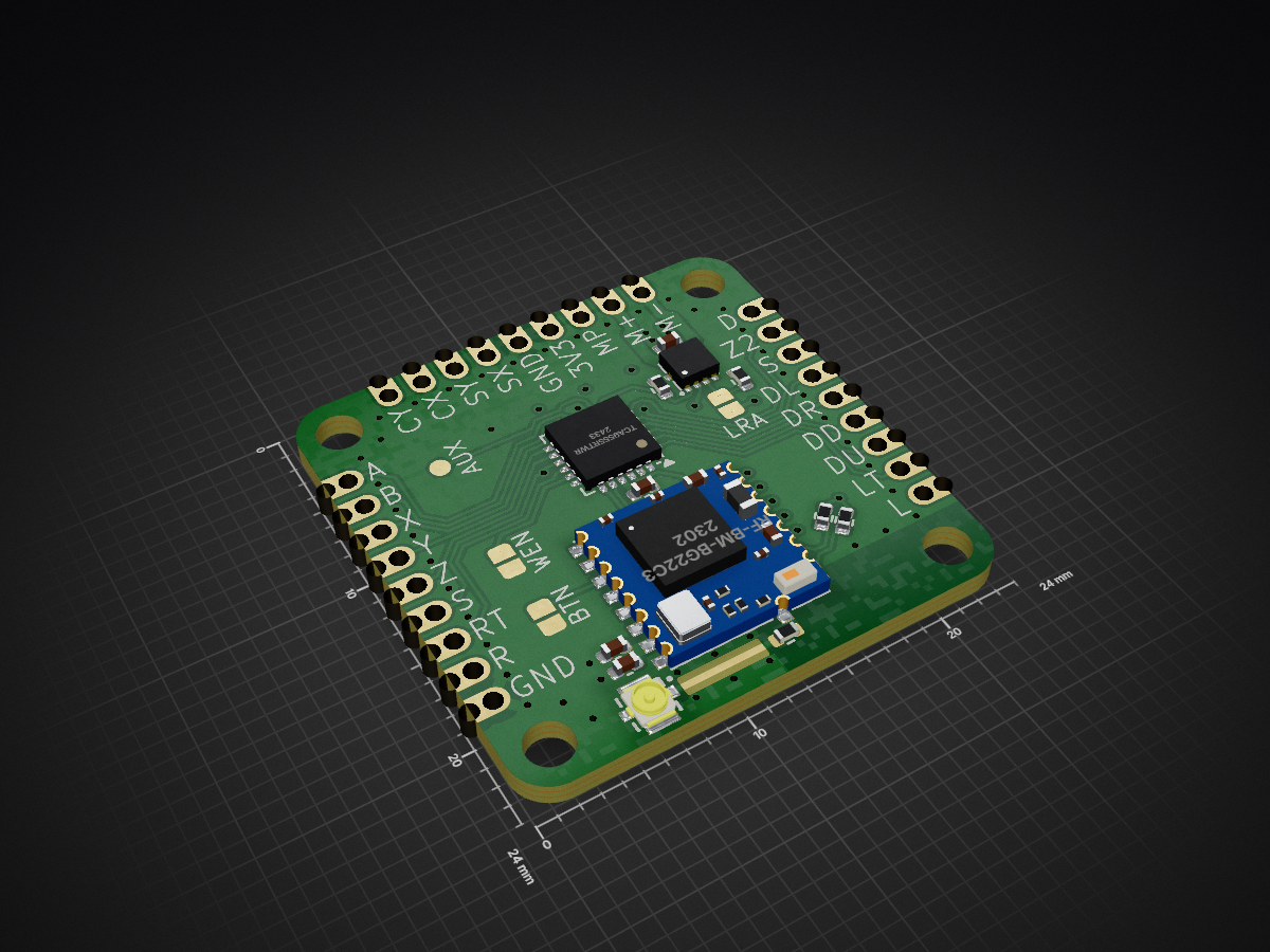
 loopj/wavephoenix-plus8
The WavePhoenix+ is a custom PCB which allows you to add WaveBird support to portable Wii/GameCube consoles. It is footprint compatible with the 4Layer Technologies GC+ 2.0 board, and emulates both a physical GameCube…
Wp plus is an open-source printed circuit board by loopj, from the loopj/wavephoenix-plus repository on GitHub. It is a 4-layer board of 24 × 24 mm with 48 parts on 38 nets, routed with 275 tracks and 77 vias.
It is built around the RF-BM-BG22C3 and TCA9555RTWR(UMW). Its parts include 5 resistors, 4 capacitors, 3 ICs and 1 connector.
[!IMPORTANT]
This is beta hardware! You'll need a copy of the WavePhoenix+ firmware from loopj to use this board, which is not yet publicly available.
The WavePhoenix+ is a custom PCB which allows you to add WaveBird support to portable Wii/GameCube consoles. It is footprint compatible with the 4Layer Technologies GC+ 2.0 board, and emulates both a physical GameCube controller, as well as a WaveBird receiver.
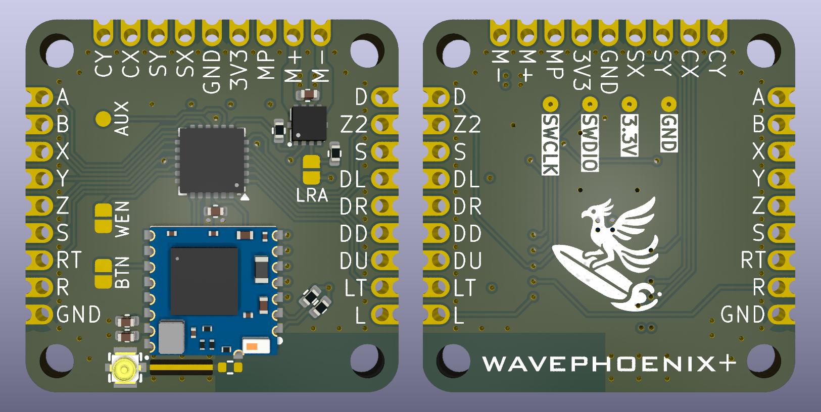
Both the WavePhoenix bootloader, and WavePhoenix+ firmware will need to be flashed to the board before it can be used. The back of the board has a set of 0.1" (2.54mm) pitch pads for flashing the bootloader via SWD.
I use a handheld pogo flashing adapter for this, but you can also temporarily hand solder wires to the pads if you don't want to buy an adapter.
See the WavePhoenix flashing docs for more information on flashing the bootloader.
Pairing controllers can be done by entering "pairing" mode. You can enter pairing mode by briefly bridging the BTN pads on the board, typically using a tact switch. Alternatively you can enter pairing mode from the WavePhoenix+ homebrew.
Once the WavePhoenix+ firmware is initially flashed, it can only be flashed again once bootloader mode is entered. To enter bootloader mode, bridge the BTN pads on the board for more than 3 seconds. Alternatively, you can enter bootloader mode from the WavePhoenix+ homebrew.
It can often be desirable to use an external antenna on builds.
To use an external antenna, you'll need to carefully remove the onboard chip antenna from the RF-BM-BG22C3 with hot air station or soldering iron. You'll then need to add a 0Ω resistor to bridge the antenna trace to the external antenna connector.
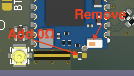
I'd recommend covering the nearby components with Kapton tape before attempting to remove the chip antenna with hot air.
You'll need to use a a 2.4GHz antenna with an IPEX MHF 4 (or compatible) connector.
The board uses a DRV2603 haptic driver for rumble support, which supports both ERM and LRA rumble motors. The board is configured to use an ERM motor by default, but you can change this by bridging the LRA pad on the board.
Wireless is disabled by default to allow for a lower power mode when in portable mode. To enable wireless, connect the top half of the WEN pads to GND.
For example, you may want to use either a physical switch or a GPIO to control the WEN pads, so that you can enable wireless when docked, and disable it when undocked.
The radio SoC uses very little power compared to a powered Wii/GameCube/N64 so it is often more convenient to just enable wireless permanently when the board is powered. To do this, simply bridge the WEN pad on the board.
The pinout of the board is identical to the 4Layer Technologies GC+ 2.0 board.
This is a very specialist project, designed for use in portable Wii/GameCube/N64 consoles where having support for a wireless controller is desirable, such as "dockable" portables.
If you are building a portable where that is not a requirement, then you should buy a GC+ 2.0 board from the fine folks at 4Layer Technologies instead.
The firmware currently does not support features such as dead zone configuration, setting stick limits, or other advanced controller options.
I will likely add support for configuring basic stick limits, and inverting stick axes via either the WavePhoenix+ homebrew, or a web browser Bluetooth UI in future.
The firmware in this repository is licensed under the MIT License.
The hardware is licensed under the Solderpad Hardware License v2.1.
| Qty | Value | Footprint | References |
|---|---|---|---|
| 5 | TestPoint | project-footprints:TestPoint_Pad_D1.0mm | TP28, TP29, TP30, TP31, TP32 |
| 3 | 0.1uF | Capacitor_SMD:C_0402_1005Metric | C1, C3, C4 |
| 3 | SolderJumper_2_Open | project-footprints:SolderJumper-Small | JP1, JP2, JP3 |
| 2 | 10K | Resistor_SMD:R_0402_1005Metric | R4, R5 |
| 2 | 2.2K | Resistor_SMD:R_0402_1005Metric | R2, R3 |
| 2 | GND | project-footprints:2x1mm Castellated Pad | TP1, TP14 |
| 2 | S | project-footprints:2x1mm Castellated Pad | TP4, TP21 |
| 1 | 0R | project-footprints:R_0402_DNP | R1 |
| 1 | 10uF | Capacitor_SMD:C_0402_1005Metric | C2 |
| 1 | 3V3 | project-footprints:2x1mm Castellated Pad | TP15 |
| 1 | A | project-footprints:2x1mm Castellated Pad | TP9 |
| 1 | B | project-footprints:2x1mm Castellated Pad | TP8 |
| 1 | CX | project-footprints:2x1mm Castellated Pad | TP11 |
| 1 | CY | project-footprints:2x1mm Castellated Pad | TP10 |
| 1 | D | project-footprints:2x1mm Castellated Pad | TP19 |
| 1 | DD | project-footprints:2x1mm Castellated Pad | TP24 |
| 1 | DL | project-footprints:2x1mm Castellated Pad | TP22 |
| 1 | DR | project-footprints:2x1mm Castellated Pad | TP23 |
| 1 | DRV2603RUNT | project-footprints:QFN-10_L2.0-W2.0-P0.50-TL | U3 |
| 1 | DU | project-footprints:2x1mm Castellated Pad | TP25 |
| 1 | Ext Ant | project-footprints:IPEX-SMD_4P-L1.7-W1.7-LS2.0-L-4 | J1 |
| 1 | L | project-footprints:2x1mm Castellated Pad | TP27 |
| 1 | LT | project-footprints:2x1mm Castellated Pad | TP26 |
| 1 | M+ | project-footprints:2x1mm Castellated Pad | TP17 |
| 1 | M- | project-footprints:2x1mm Castellated Pad | TP18 |
| 1 | MP | project-footprints:2x1mm Castellated Pad | TP16 |
| 1 | R | project-footprints:2x1mm Castellated Pad | TP2 |
| 1 | RF-BM-BG22C3 | project-footprints:RF-BM-BG22C3 | U1 |
| 1 | RT | project-footprints:2x1mm Castellated Pad | TP3 |
| 1 | SX | project-footprints:2x1mm Castellated Pad | TP13 |
| 1 | SY | project-footprints:2x1mm Castellated Pad | TP12 |
| 1 | TCA9555RTWR | Package_DFN_QFN:WQFN-24-1EP_4x4mm_P0.5mm_EP2.45x2.45mm | U2 |
| 1 | X | project-footprints:2x1mm Castellated Pad | TP7 |
| 1 | Y | project-footprints:2x1mm Castellated Pad | TP6 |
| 1 | Z | project-footprints:2x1mm Castellated Pad | TP5 |
| 1 | Z2 | project-footprints:2x1mm Castellated Pad | TP20 |
It measures 24 × 24 mm and has 4 copper layers, 1.2 mm thick.
48 parts, built around the RF-BM-BG22C3 and TCA9555RTWR(UMW). The full list of its parts is on this page, with links to each part's symbol and footprint where PCBKit's library has them.
From the loopj/wavephoenix-plus repository on GitHub, at the commit this page was made from: the board is hardware/KiCad/wp-plus.kicad_pcb and its schematic hardware/KiCad/wp-plus.kicad_sch. PCBKit opens the board in the browser, with nothing to install.
Its repository states no licence, so its author keeps all rights: ask loopj before reusing the design.
borgel/bolton_buttons
Small devices to add keys to devices that have too few


sudo-junkie/Controller
ESP32-based replacement PCB for UCOM USB game controller, with LCD, IMU, IR TX/RX and more...


hossainmahmudchowdhury-boop/20-key-macropad
A small 20-key MacroPad built around the Seeeduino XIAO microcontroller. It has a custom circuit board. The MacroPad has 20 keys in a 4×5 grid.

sillevl/spha-btni-hardware
SPHA 16-channel input module with microcontroller, input/output circuitry, and CAN connectivity.

sillevl/spha-rel6-hardware
Open the .kicadpro file in KiCad. The design includes files originating from an older KiCad workflow; review schematic links, footprints, design rules, zones, and manufacturing outputs after any conversion or upgrade.