Skip to the content
PCBKitNew board
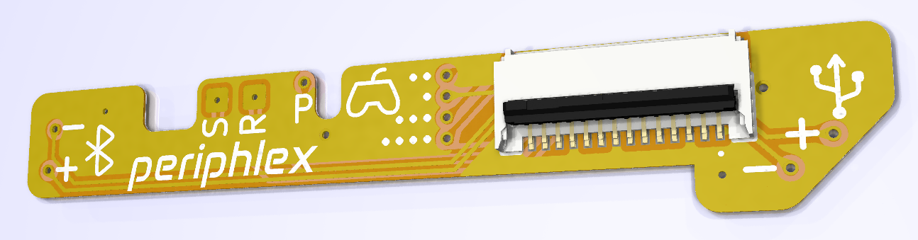
2 layers33.8 × 6.2 mmPeriphlex, the printed circuit board in 3D

Flex PCB breakout for Bluetooth, USB, GameCube controller ports on trimmed Wii motherboards

Size
33.8 × 6.2 mm
Copper layers
2
Thickness
0.22 mm
Parts
14
Nets
12
Pads
29
Tracks, vias
75, 10
Pours
33
Routed
Yes
KiCad
KiCad 8.0 (file 20240108)
Created
22 Feb 2024
Updated
2 Mar 2024

Overview

Periphlex is an open-source printed circuit board by loopj, from the loopj/periphlex repository on GitHub. It is a 2-layer board of 33.8 × 6.2 mm with 14 parts on 12 nets, routed with 75 tracks and 10 vias.

It belongs with the radio and wireless and computers and single-board computers boards of this library.

README

README.md

Flex PCB breakout for Bluetooth, USB, GameCube controller ports on trimmed Wii motherboards

Why?

Building a Wii portable requires trimming a Wii motherboard and relocating key peripherals such as USB, Bluetooth, and GameCube controllers. This design breaks out these peripherals from the front of the board to a low-profile FFC connector, allowing for more modular builds.

The board is designed to be semi-permanently installed by soldering to exposed traces for the USB and Bluetooth data lines, and to the vias for the GameCube ports.

Features

  • Solders directly to the top of a Wii motherboard
  • 14-pin FFC low profile connector fits cleanly underneath heatsinks/plates
  • Fits within the footprint of all but the most aggressive Wii trims
  • Breaks out frequently used peripheral lines
    • Bluetooth data
    • USB data
    • GameCube controller data (x4)
    • Reset GPIO (via magnet wire)
    • Soft shutdown GPIOs

BOM / Ordering

  • Grab the Gerber files for the latest release
  • Order a 2-layer, 0.5oz copper flex PCB from JLCPCB, PCBWay, Gold Phoenix, or similar
  • Purchase a Molex 503480-1400 connector (DigiKey, Mouser)
  • Purchase a 14 pin, 0.5mm pitch FFC cable of desired length

Installation

  • Solder the FFC connector to the flex PCB
  • Line up the 4 GameCube vias in the middle of the PCB with the GameCube vias on the front of the Wii motherboard, and tape into place
  • Mark the position of the holes for Bluetooth and USB using a fine sharpie through to the Wii motherboard
  • Remove the flex and inspect the marks, they should be over the traces
  • Carefully expose the traces for Bluetooth and USB at the marked locations
    • Use a fine craft knife or dental pick to scratch the solder mask off the correct trace
    • Be careful to not expose the neighboring trace
    • Clean the exposed traces
  • Line up the PCB with the GameCube vias again and tape into place
  • Solder the following vias on the flex to the motherboard
    • The four GameCube vias
    • The Bluetooth and USB vias (to the exposed traces)
    • The POWER GPIO via (P)
    • The GND via at the top right of the "X" of the logo
    • The GND via to the right of the connector
  • Solder a magnet wire from the "R" pad to the Reset via on the opposite side of the board
  • Solder a magnet wire from the "S" pad to the SHUTDOWN GPIO via on the opposite side of the board
  • Test for continuity, and secure in place with CA glue or kapton tape

Installation tips

  • Remove any excess soldermask from the vias on the motherboard you'll be soldering to
  • Pre-tin the vias first
  • I like to tin the bottom of the corresponding vias on the flex
  • Use lots of flux

FFC Pinout

1234567891011121314
USB-USB+GNDGC4GC3GC2GC1GNDBT- (Data 2)BT+ (Data 1)GNDS PadR PadPOWER GPIO

Pin 1 is the right-most pin on the FFC, indicated with a dot.

Don't forget that these pin numbers will likely be reversed on the opposite end of your FFC cable, depending on the connector/cable you use.

Future enhancements

  • Could potentially also break out the USB1 data lines in future

License

Permissively released under the Solderpad Hardware License v2.1

Parts

14
QtyValueFootprintReferences
11TestPointproject-footprints:ViaPad_0.3_0.5TP1, TP2, TP3, TP4, TP5, TP6, TP7, TP8, TP10, TP11, TP12
2TestPointproject-footprints:TestPoint_Pad_1.0x1.0mmTP9, TP13
15034801400project-footprints:5034801400J1

Questions

How big is the Periphlex PCB?

It measures 33.8 × 6.2 mm and has 2 copper layers, 0.22 mm thick.

What parts does the Periphlex use?

14 parts. The full list of its parts is on this page, with links to each part's symbol and footprint where PCBKit's library has them.

Where can I download the Periphlex KiCad files?

From the loopj/periphlex repository on GitHub, at the commit this page was made from: the board is KiCad/periphlex.kicad_pcb and its schematic KiCad/periphlex.kicad_sch. PCBKit opens the board in the browser, with nothing to install.

Can I use the Periphlex design in my own project?

Its repository states no licence, so its author keeps all rights: ask loopj before reusing the design.

Similar boards

  • 2 layers116.8 × 30 mmType d, the printed circuit board in 3D

    Type d

    google/mozc-devices

    Circuit diagrams and firmware source code for Gboard DIY keyboards

    14 parts3kApache-2.0
  • 2 layers32 × 22 mmDiff driver, the printed circuit board in 3D

    Diff driver

    rene-dev/stmbl

    AC Servo Driver for STM32F4

    14 parts990GPL-3.0
  • 2 layers34 × 45 mm2032Charger, the printed circuit board in 3D

    2032Charger

    hackclub/OnBoard

    💡 Join 1,000 teenagers and make your first PCB with a $100 grant!

    14 parts915
  • 2 layers34 × 109.9 mmTdisplay s3, the printed circuit board in 3D

    Tdisplay s3

    landonr/homeThing

    Wifi Smart Home Remotes that run on ESPHome

    14 parts551GPL-3.0
  • 2 layers45.3 × 42.7 mmMainPcb, the printed circuit board in 3D

    MainPcb

    adamb314/ServoProject

    Getting the most out of your hobby servo

    14 parts545
  • 2 layers42.5 × 28.8 mmC5VRX JACK DIY, the printed circuit board in 3D

    C5VRX JACK DIY

    Twotoz/C5VRX

    Ultra-minimal, zero-CPU 5.8 GHz analog FPV video receiver using ESP32-C5 Wi-Fi 6 PHY MODEM_DIAG, BitScrambler WBFM demodulation & resistor DAC CVBS

    14 parts515GPL-3.0
  • 2 layers62 × 24 mmMai button, the printed circuit board in 3D

    Mai button

    whowechina/mai_pico

    Pico controller for Maimai

    14 parts475