Skip to the content
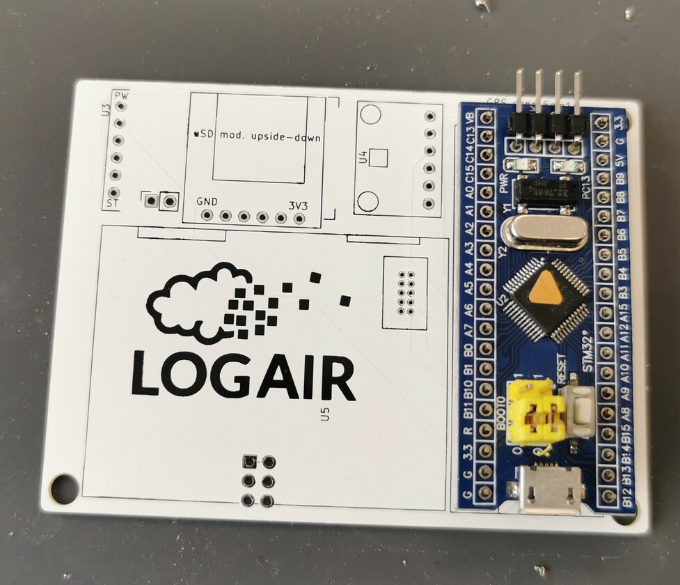
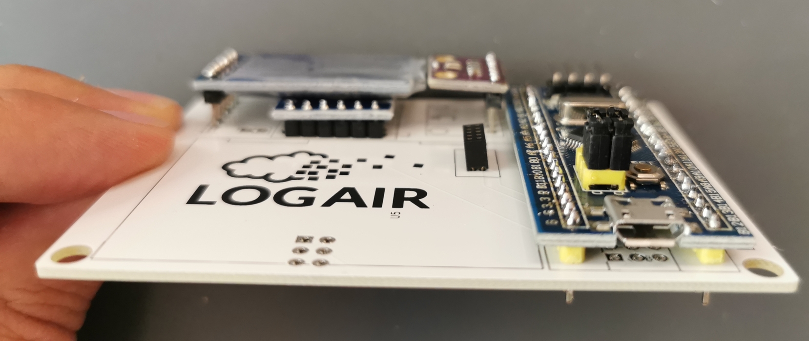
2 layers80 × 60 mmLogair diy, the printed circuit board in 3D

Blueprints of LogAir particulate matter monitor

Size
80 × 60 mm
Copper layers
2
Thickness
1.6 mm
Parts
12
Nets
52
Pads
99
Tracks, vias
167, 0
Routed
Yes
KiCad
KiCad 5 (file 20171130)
Created
17 Oct 2019
Updated
29 Nov 2021

Overview

Logair diy is an open-source printed circuit board by logair, from the logair/LogAir-Device-DIY repository on GitHub. It is a 2-layer board of 80 × 60 mm with 12 parts on 52 nets, routed with 167 tracks and 0 vias.

It is built around the PMS7003M and BME280. Its parts include 7 ICs and 4 connectors.

Main components

2

README

README.md

Hardware docs for the DIY LogAir device

  • Schematics
  • PCB
  • BoM
  • Arduino code

The hardware as it is streams, once per second, the following data through BLE and to the uSD card: Latitude, Longitude, Altitude, Speed, Heading, Temperature, Relative Humidity, Atmospheric Pressure, PM1, PM2.5, PM4, PM10

The Arduino-compatible MCU is a Bluepill, a generic implementation of the STM32F103. The chip is flashed with a code compiled with the Arduino IDE and the following libraries: NeoGPS, PMS Library, BME280, SdFat.

The data transmissio nprotocol is extensible to allow implementation of different sensors.

How To

Assemble

Click to expand for instructions!

Material

  • LogAir PCB

  • Bluepill + connectors

  • BME280 + connector

  • uSD module

  • BLE module

  • PMS7003 + connector

  • DC step-up

  • Charger module

  • GPS module

  • Soldering iron + tin

  • double-sided tape + jelly tape if available

  • cutting pliers

  • flat pliers

    Instructions

  1. A very first step should be to try and upload code to the Bluepill. This is before the rest as it happened that the chips could not be programmed, and realizing that after all that work is not ideal. Upload a bootloader, a blink code, and there you go.

  2. Solder the Bluepill connectors. Use the holes in the PCB as a guide for alignment. The G (GND, ground) pins are harder to solder, because of the copper mass involved.

  1. Solder the assembled Bluepill to the PCB. Pay attention to the orientation.
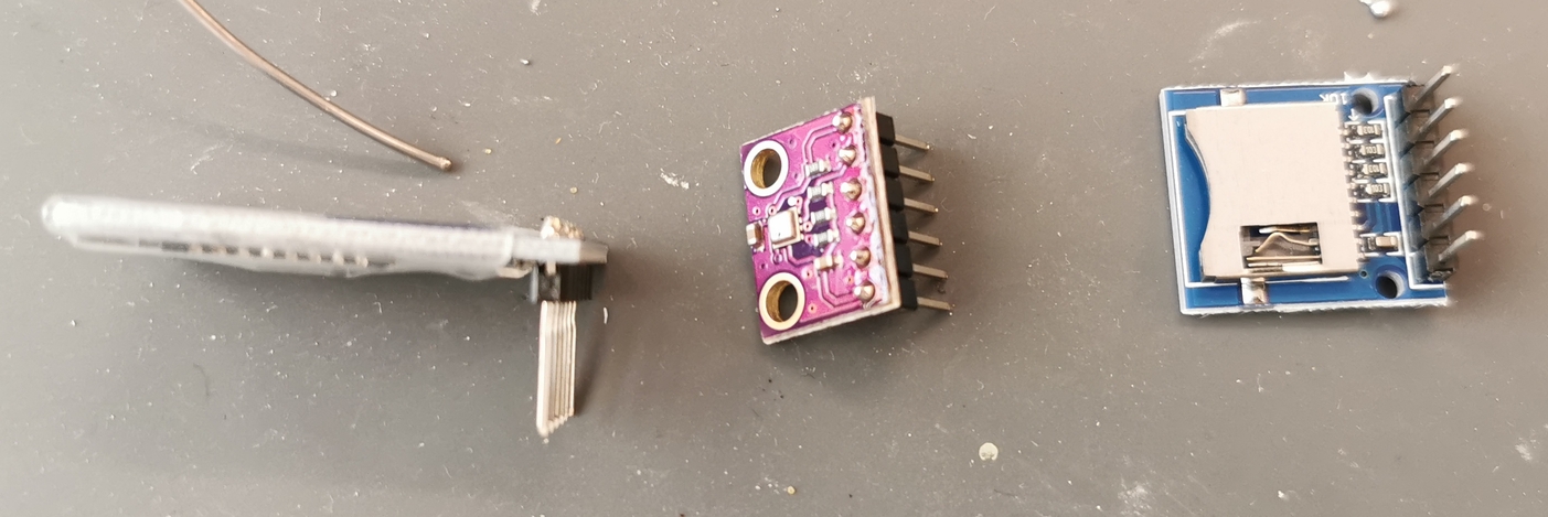
  1. Prepare the BME280 (solder the connectors), the BLE module (straighten the pins with a flat plier), and the uSD module
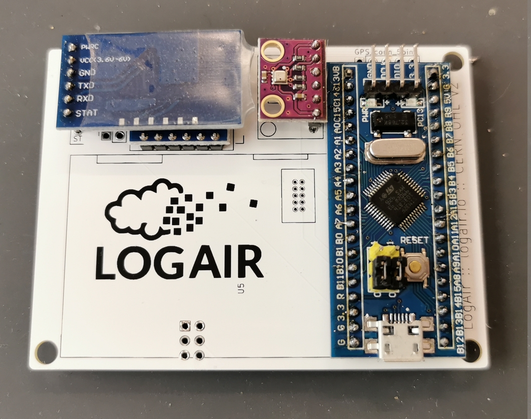
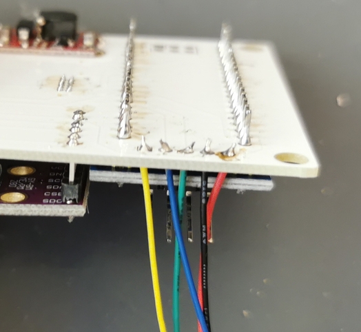
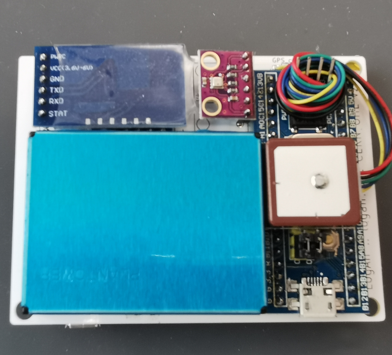
  1. Place the BLE, BME, and uSD modules. Follow the picture, the BME280 (violet module) should be as far as possible from the PCB), with its pins barely sticking through on the other side.
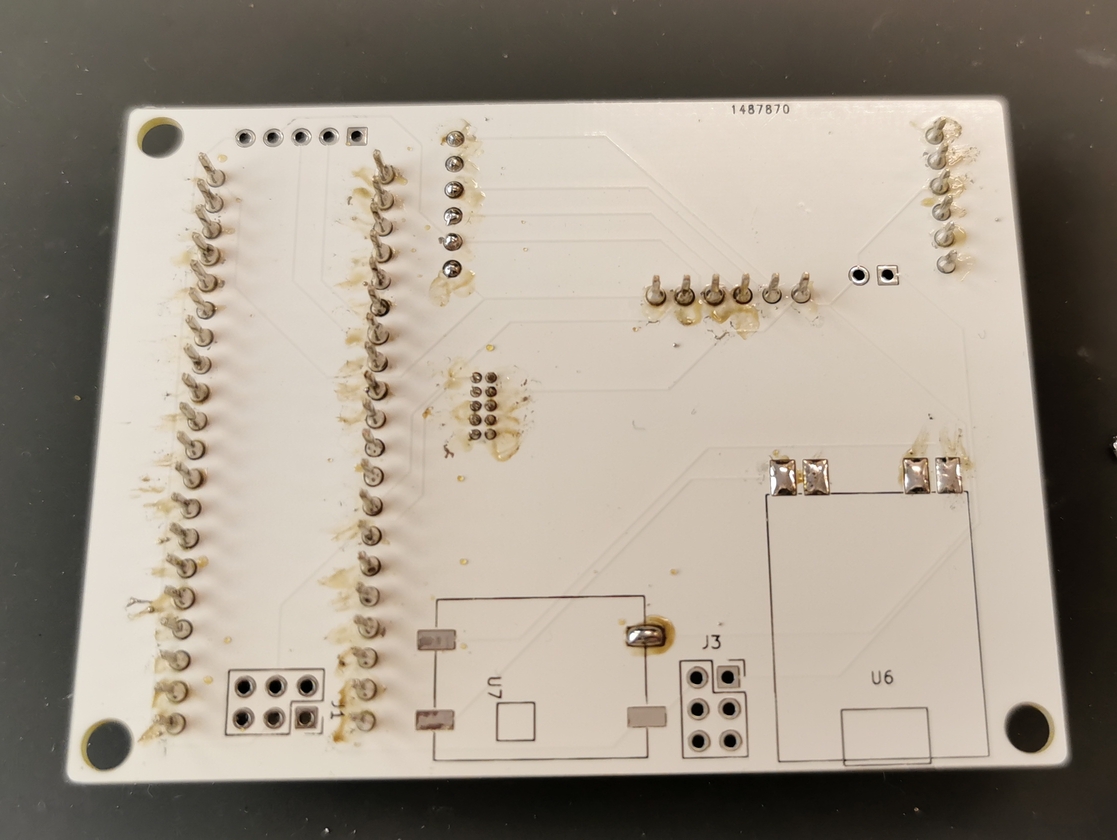
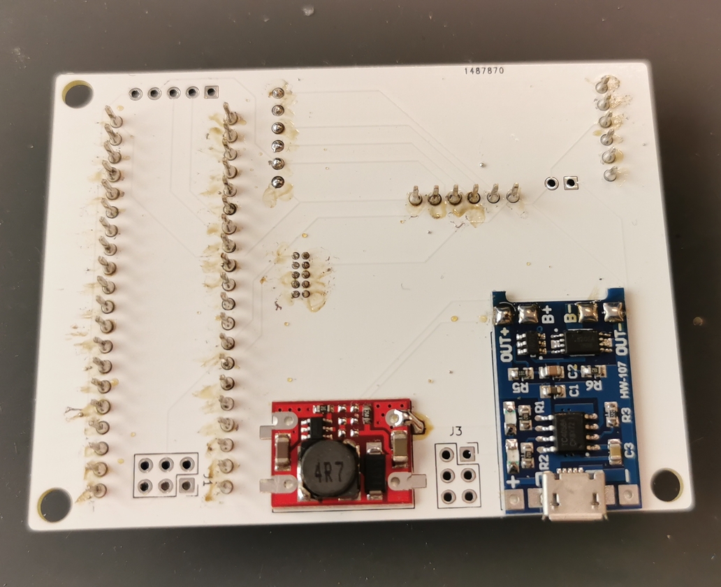
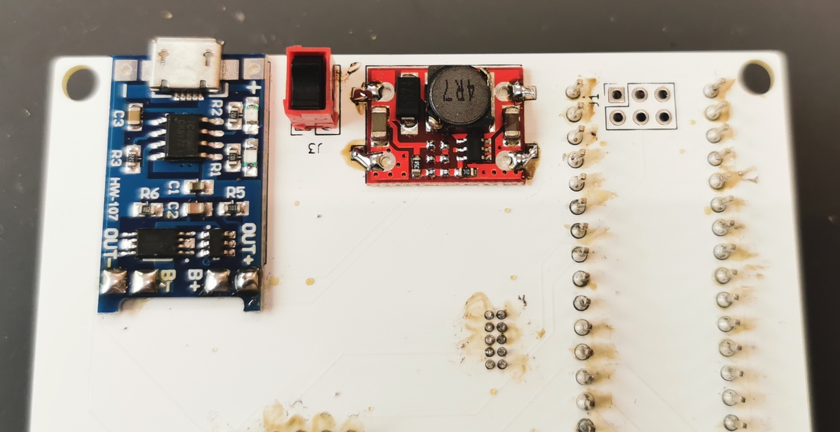
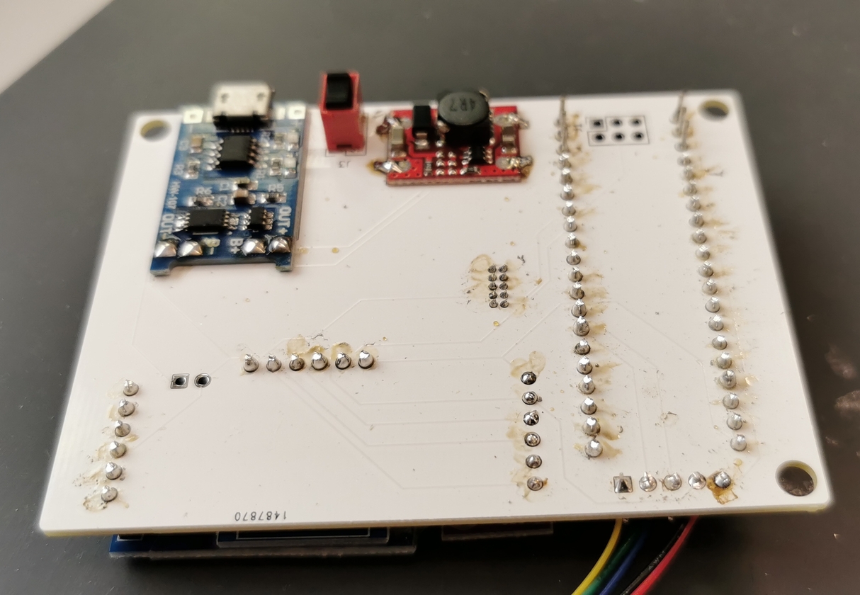
  1. Prepare the PCB for the power modules: put a thin layer of tin on the (blue) charger module pads, and a solder blob on one of the (red) step-up pads
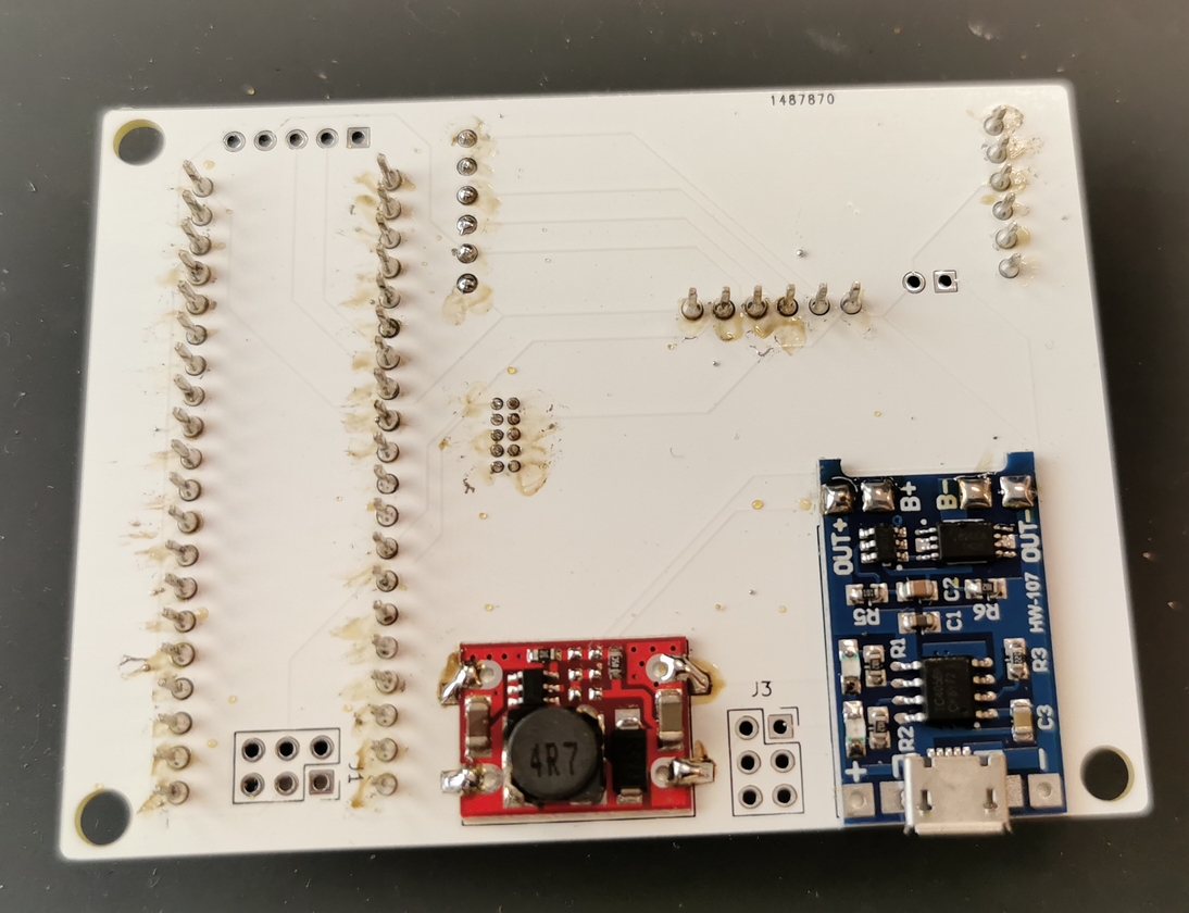
  1. Solder the charger module by putting it in place, and adding solder on the pads from the top. I count about 5 seconds of applying heat for the tin applied on step 5 to melt. Then solder the step-up module using the first pad to hold it in place. When you are done, check the conductivity between the pins of the two modules, and that between the pads of the charging module. The latter because the method used to solder can produce 'tin overflows'.

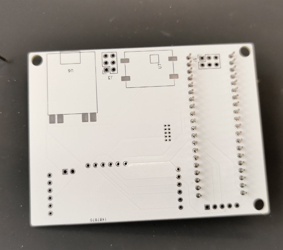
Then place and solder the switch. Here, try to apply a minimal amount of tin. As the other side of the pins will go against the PMS7003 which has a conductive casing, the pins should be cut or filed down, then taped over (two layers of normal, clear tape are enough)

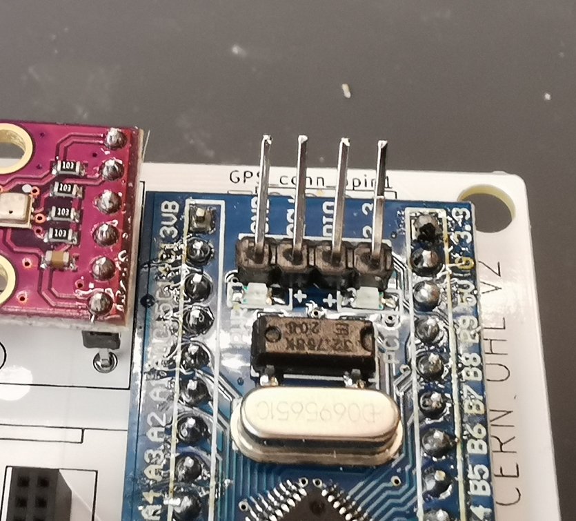
  1. Bend lightly the SWD pins of the Bluepill to give room for soldering the GPS wires
  1. Solder the GPS wires. The order is the same as their order on the GPS-side plug, you can use the PCB markings (5V is red) and pictures to help you. The wires should not go over each other at any point for the order to be preserved.
  1. Solder the connector for the PMS7003. As the width of the Bluepill vary a bit, it is safer to solder it lightly 'bent' away from the bluepill. To do that, solder the pins that are on the far side from the Bluepill first, then plug the PMS7003 in to see how thing fit. Then remove and solder the rest. 5-10 degrees should do.
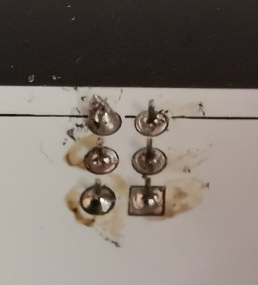
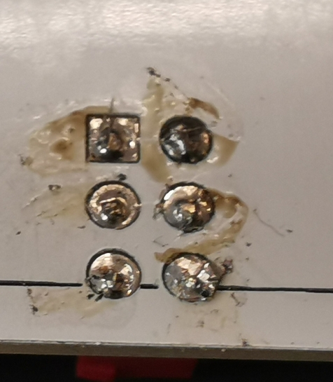
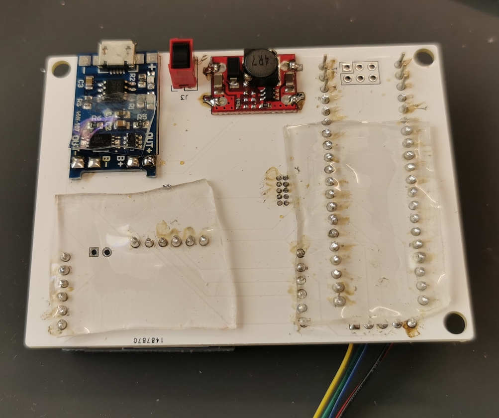
  1. For a smaller device, I cut most of the pins apparent on the back of the PCB to the top of the tin cone. Apply insulation on the pins, and this is important. I use a sticky, translucent, think tape I found on aliexpress. Any other ~1-2mm insulating material will easily do.
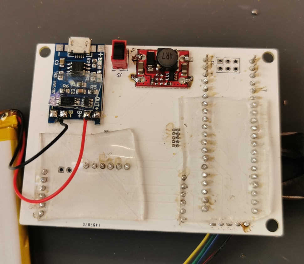
  1. Solder the battery wires to the charger module pads
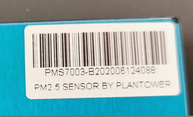
  1. Before finalizing the assembly, write down the PMS7003 serial number somewhere, to track device quality :)
  1. And it is done :)

Program

Click to expand for programming instructions!

Pre-requisites

  • A Bluepill with functional bootload (e.g. generic_boot20_pc13.bin from https://github.com/rogerclarkmelbourne/STM32duino-bootloader
  • Install Arduino IDE
  • Install board definition:File > Preferences > Additional Boards Manager URLs: add the following URL to the list (empty by default): https://github.com/stm32duino/BoardManagerFiles/raw/main/package_stmicroelectronics_index.json
  • Tools > Board > Boards Manager > Search 'STM32' > Install 'STM32 MCU based boards'
For older instructions using unofficial stm32duino core
  • Install board definition:File > Preferences > Additional Boards Manager URLs: add the following URL to the list (empty by default): http://dan.drown.org/stm32duino/package_STM32duino_index.json
  • Tools > Board > Boards Manager > Search 'STM32' > Install 'STM32F1xx/GD32F1xx boards'
  • Once done, close the Board Manager and Select the Board: Tools > Board > STM32F1 Boards (Arduino_STM32) > Maple mini

NO NEED TO FOLLOW THE CONFIGURE SECTION BELOW.

Configure

  • Select the proper board: Tools > Boards > STM32 Boards (selected from submenu) > Generic STM32F1 series
  • Enable configurations we need:
    • Tools > U(S)ART Support > Enabled (Generic 'Serial')
    • Tools > USB Support > CDC (Generic Serial supersedes U(S)ART)
    • Tools > Upload Method > Maple DFU Bootloader 2.0

Libraries

Install the following libraries from the Library Manager Tools > Manage Libraries...

  • NeoGPS: Install, and replace the contents of $HOME/Arduino/libraries/NeoGPS/src/GPSport.h by:
text
#ifndef GPSport_h
#define GPSport_h

#define gpsPort Serial2
#define GPS_PORT_NAME "Serial2"
#define DEBUG_PORT Serial

#endif
  • BME280 by Tyler Glenn
  • PMS Library by Mariusz Kacki

Connect, compile and upload

Let us now try and upload a quick code to test if all works...

  • Open the Blink example, and add #define LED_BUILTIN PC13 at the very beginning
  • Select the Port: Tools > Port > ... (depends on your OS)
  • Press the Compile and Upload arrow....

If the upload does not go through, this might be because the board cannot auto-reset with your computer. To upload, you will need to manually reset by pressing the button you can see near where the GPS chip is stuck just before pressing the Compile arrow. It takes a bit of trial and error and some OS's need it while some others don't.

Upload the LogAir code

Download the code from the repository, and follow the same process as above.

Connect

UART parameters to connect to the serial monitor are the ones set in the code. The default is 112500, but 9600 was previously used.

Troubleshoot

Board appears in dmesg, but not in lsusb

You might need to create a udev rules file /etc/udev/rules.d/45-bluepill.rules

text
ATTRS{idVendor}=="1eaf", ATTRS{idProduct}=="0004", MODE="0666" SYMLINK+="maple", ENV{ID_MM_DEVICE_IGNORE}="1"
ATTRS{idVendor}=="1eaf", ATTRS{idProduct}=="0003", MODE="0666" SYMLINK+="maple", ENV{ID_MM_DEVICE_IGNORE}="1"

Use

Click to expand for usage instructions!

Turning ON / OFF

The switch onthe back of the device allows to turn the device on and off.

The red or green blinking light shows when the device is writing on the SD card. When the LED is ON, the device should not be turned OFF as it might corrupt the card.

Blinking LEDs

The modules we use include LEDs of varying colors. Here are some useful informations you can get from them:

  • Bluetooth LED (green or red), left side of the device: This LED is blinking if no phone is connected to the device, and stays on when a connection is active.
  • GPS LED (blue and red):
    • The red LED shows the module is powered, and should always be on when the device runs.
    • The blue LED is blinking when the module receives signals strong enough to get a 'fix', or know its position. This is important if you rely on the SD card only to record the measurements, i.e. if you're not using a smartphone to send your data to the server.
  • Device LEDs:
    • Left LED: red or green, signals the controller receives power. Should always be ON when the device is turned on.
    • Right LED: red or green, currently parametered to signal the device is writing to the SD card and should not be powered off. You can turn the device OFF when the LED is OFF.

With the LogAir APP

Follow the instructions on our video tutorial.

Stand-alone

The LogAir device records its measurements on the micro-SD card, which can be extracted and imported into a spreadsheet or GIS program.

The limitation in this mode is that the device can only rely on its own GPS module for time and position. This means that, before a valid GPS signal is acquired, the measurements on the SD card will not list any time or position.

The signal depends on your location, the time of the day, if there are obstacles between the device and the sky, etc. Indoor measurements are often difficult, but windowsills sometimes give good results.

We are trying to find a way to give the current time to the device by using a program on the computer, or preparing it on the SD card, but there is no easy solution there... See ToDos, input welcome :)

ToDo

Here are several items that are planned, currently developed, or on hold pending contributions. If you are interested in any of them be it for giving a helping hand or advices, please get in touch :)

Hardware

These items focus on the device conception, including electronics, casing, production, etc.

Click to expand for Hardware development tasks!
  • Disconnect PC14 and PC15 for RTC reliability
  • Better power supply, as this one just charges and discharges blindly.
  • Integrate the components on a printed circuit board
  • Replace the BLE module with an ESP32 (the STM32 might have to stay, as ESP32 are more limited, e.g., available UARTs)
  • Make a similar MVP with SPS30 & SHT3x
  • Add a LoRa chip! See Clement's work
  • ...

Firmware

Firmware development focuses on the program that makes the device run. The brain within the machine :)

Click to expand for Firmware development tasks!
  • Provide a time base when no GPS signal is present, and no phone is connected
    • Implement RTC (there is an on-board crystal on the Bluepill).
    • Implement time input from serial (BLE and/or PC)
  • Implement better data storage and upload
    • Log data with human-readable time as well as UNIX timestamp
    • Revamp buffering to limit uSD write operations
    • Revamp data storage on the SD card (textfile + DB?)
    • Implement deferred data upload for when uplink not continuously available
  • Implement online GPS config: some changes to the embedded GPS FW are sometimes necessary for best operation
    • Get and store almanach/ephemeris on uSD card! This would really help with no-phone collection
    • Other generic config, constellations, accuracy requirements, etc.
  • Implement component recognition: find out which sensors are used from their output stream (starting with PM sensor)
  • Add interrupts everywhere?
  • ...

APP

Here, developmetn of our application that helps collect and send data from the device to the servers, and get it back in forms of maps, messages, etc. Our UI sucks? Contribute a better one ;)

Click to expand for APP development tasks!
  • All

    • Implement API key for upload/download
  • Android version

    • APP should check at startup that GPS is enabled (and available in background if knowable) and prompt if not.
    • Make it simpler: no settings, sending all packets stored every 10sec, etc
    • Auto-connect: priority to previously connected devices, then to '.logair.', etc
    • Map should be loaded at startup, not only when map tab is opened
    • ...
  • iOS version

    • Make one :x Nicos is on it!
    • ...

Backend

All the work that helps gather the data, safekeep it, develop ways to use it, share it, etc. DBs, services, APIs and the like. Put your hoodie on and hack away!

Click to expand for Backend development tasks!
  • Implement API key for upload/download
  • ...

Data

All the work that develop ways to analyse, understand and use the data. Algorithms, GIS, dashboards etc.

Click to expand for Data visualisation and Data science tasks!
  • Make a dashboard!
  • Build a QGIS server that works fast enough
  • Find missing data points in the contributions, and signal them for collection
  • Find periods in the signal, and exploit them
  • Build a better pipeline for extraction and analysis

Upcoming

  • Arduino library configs
  • ToDo list updates
  • Assembly instructions (video?)

Licensed under CERN OHL v.1.2 or later

Parts

12
QtyValueFootprintReferences
2Conn_01x02_FemaleConnector_PinSocket_2.54mm:PinSocket_1x02_P2.54mm_VerticalJ2, J4
1BLE_JDY-23logair_diy:BLE_JDY-23_vert_unfoldU3
1BME280logair_diy:BME280_SPIU4
1Charger_basiclogair_diy:Charger_basicU6
1Conn_01x05_FemaleConnector_PinHeader_2.54mm:PinHeader_1x05_P2.54mm_VerticalGPS_conn_5pin1
1Conn_02x03_Odd_EvenConnector_PinHeader_2.54mm:PinHeader_2x03_P2.54mm_VerticalJ1
1Conn_02x03_Odd_Evenlogair_diy:Logair_switch_2J3
1DC-DC_step-uplogair_diy:DC-DC step-upU7
1LogairBluepilllogairbluepill:LogairBluepillU1
1PMS7003logair_diy:PMS7003_10pinU5
1uSD_adapterlogair_diy:uSD_adapterU2

Similar boards

  • 2 layers70.1 × 43.2 mmIaq device, the printed circuit board in 3D

    Iaq device

    nkitanov/iaq_board

    IAQ Board is a DIY (Do-It-Yourself) device for measuring internal air quality

    19 parts396
  • 4 layers127 × 46 mmMotherboard, the printed circuit board in 3D

    Motherboard

    KhazAkar/espws

    [MOVED to GitLab: https://gitlab.com//r3xxar/espws] Weather station firmware for ESP8266 - mirror

    116 parts4MIT
  • 2 layers162 × 60 mmAir detector, the printed circuit board in 3D

    Air detector

    shm-dmitry/air-detector

    Air status sensor with hass integration and fan control

    132 partsApache-2.0
  • 2 layers99.9 × 99.9 mmAirquality, the printed circuit board in 3D

    Airquality

    sebastius/airquality

    A module based air quality sensor

    46 parts14CC0-1.0
  • 2 layers66 × 99.7 mmAirMon, the printed circuit board in 3D

    AirMon

    SG-O/airMon

    ESP32 based air quality monitor PCB

    130 parts2CC-BY-4.0
  • 2 layers49 × 50.4 mmAirMonitor, the printed circuit board in 3D

    AirMonitor

    JJendryka/AirMonitor

    60 parts
  • 2 layers71 × 74 mmParticle sensor pcb, the printed circuit board in 3D

    Particle sensor pcb

    squishykid/particles

    Particulate Matter Sensor Device

    46 parts
  • 2 layers60 × 112 mmPmco kicad, the printed circuit board in 3D

    Pmco kicad

    sugaat/low-cost-aqi-monitor

    esp32 based aqi monitor for pm, co, temperature and humidity

    8 parts

Questions

How big is the Logair diy PCB?

It measures 80 × 60 mm and has 2 copper layers, 1.6 mm thick.

What parts does the Logair diy use?

12 parts, built around the PMS7003M and BME280. The full list of its parts is on this page, with links to each part's symbol and footprint where PCBKit's library has them.

Where can I download the Logair diy KiCad files?

From the logair/LogAir-Device-DIY repository on GitHub, at the commit this page was made from: the board is pcb/kiCad/logair_diy.kicad_pcb. PCBKit opens the board in the browser, with nothing to install.

Can I use the Logair diy design in my own project?

Its repository states no licence, so its author keeps all rights: ask logair before reusing the design.