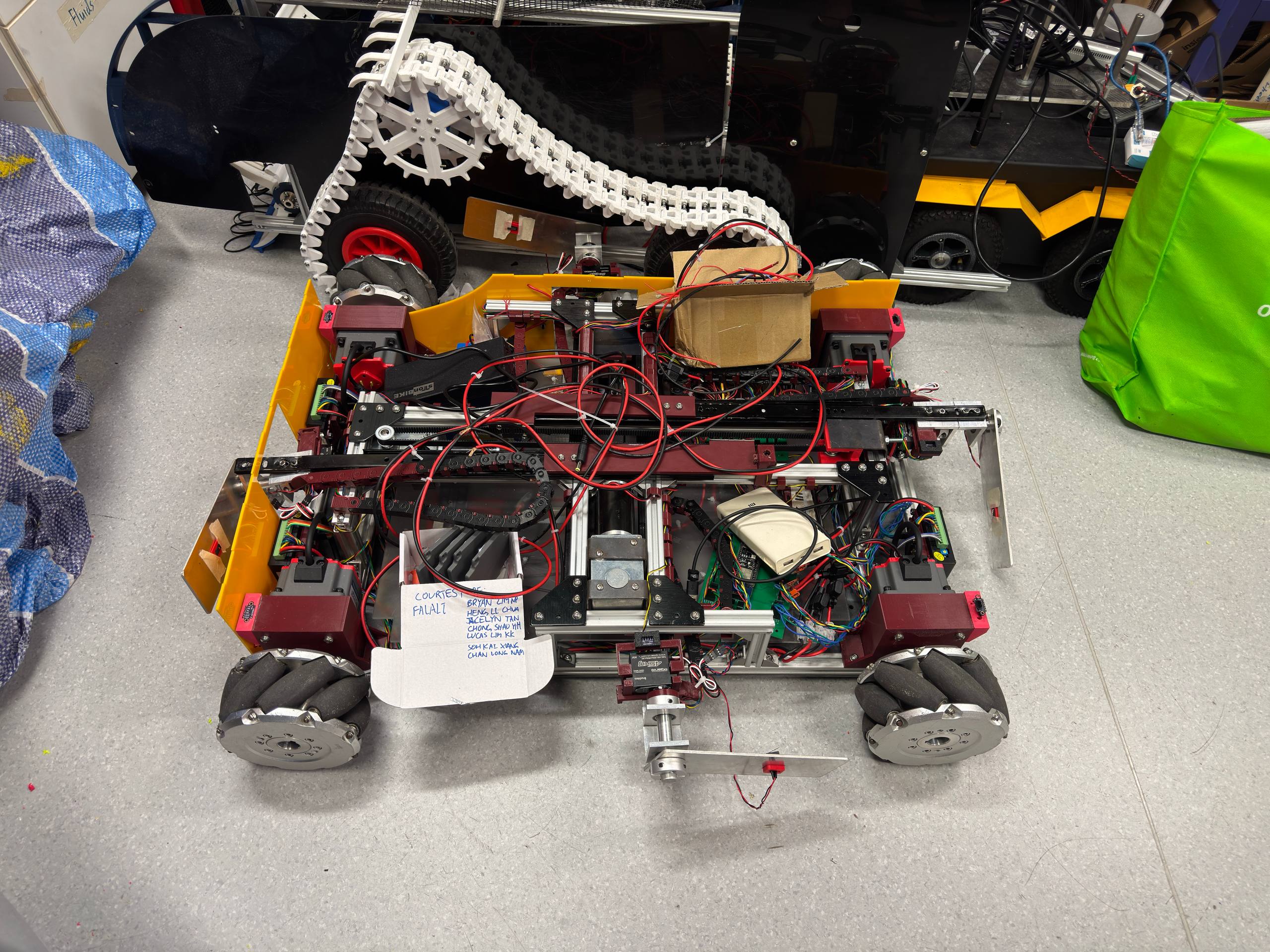
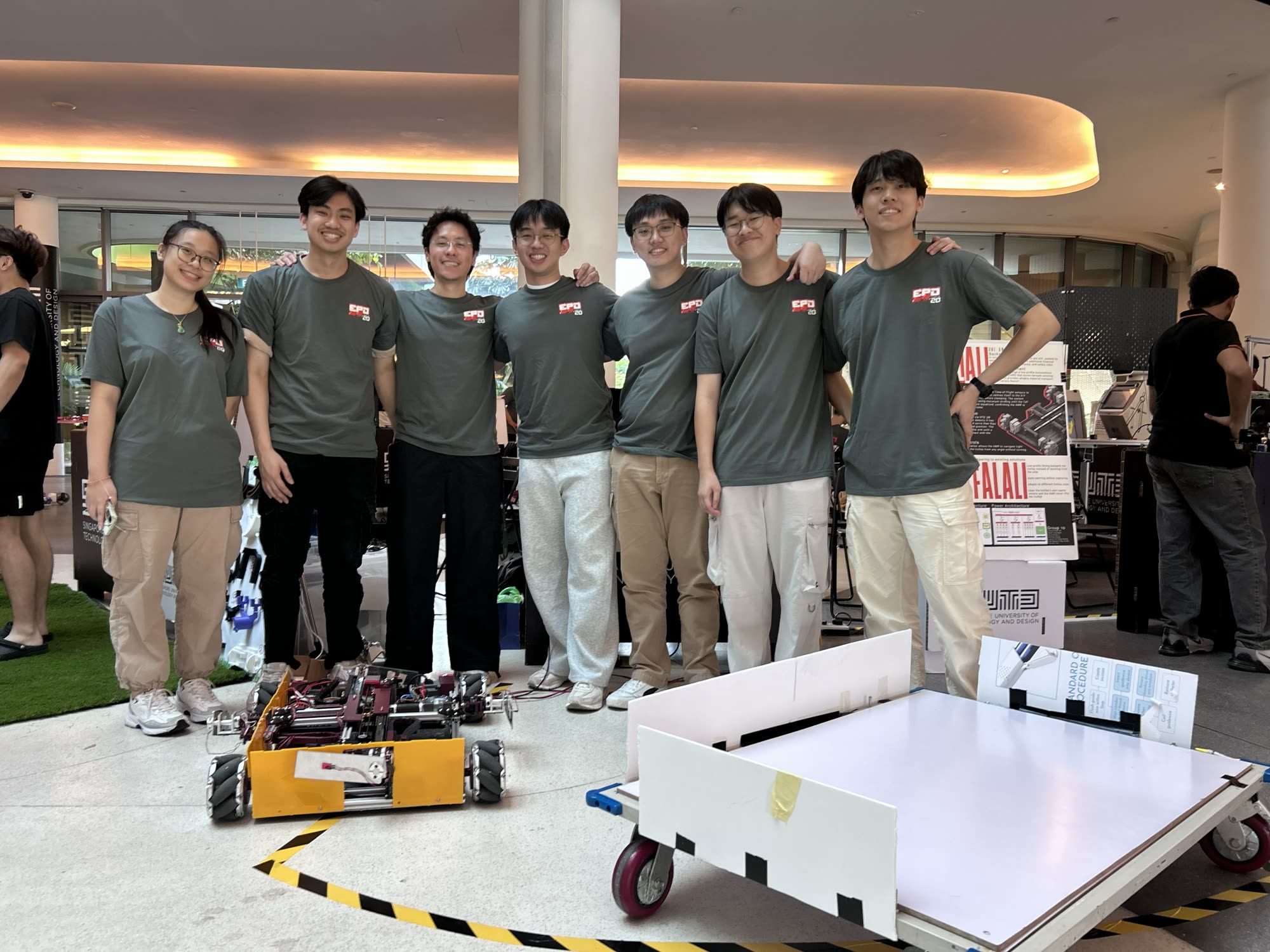
An AMR-style under-ride platform that drives beneath a textile trolley, uses upward-facing time-of-flight sensors to confirm it is under the trolley and centred, clamps onto the underside, and then moves the trolley.
Driver PCB is an open-source printed circuit board by lnpanini, from the lnpanini/Falali repository on GitHub. It is a 2-layer board of 42.8 × 33.8 mm with 16 parts on 12 nets, routed with 60 tracks and 0 vias.
Its parts include 7 resistors, 3 transistors and 2 connectors.
README
README.md
Falali — a 30.007 project
An AMR-style under-ride platform that drives beneath a textile trolley, uses upward-facing
time-of-flight sensors to confirm it is under the trolley and centred, clamps onto the
underside, and then moves the trolley. ESP32-S3 firmware, hardware and documentation.
This is also the whole-project home for Falali — One AMR Fits All (SUTD 30.007 Engineering
Design Innovation, Group 10): a low-profile autonomous mobile robot that moves existing fabric
trolleys in a textile factory by driving underneath them, clamping on, and transporting them —
no changes to the trolleys or the factory floor.
Hardware documentation lives in docs/hardware/ — power-up runbook,
component list, per-connector pinouts for all three PCBs (extracted from the KiCad netlists, not
inferred), and a fabrication/repair guide. docs/hardware-architecture.md
is the older companion and is partly superseded by it. The pin table further down this README is
the pre-PCB design intent and does not match the fabricated board.
Passed — load moved with two people standing on top
Clamp holding force
≥ 300 N
Weakest-link analysis: clamp capacity 403 N (SF 1.34×)
Clamp vertical reach
≥ 200 mm
Met
Docking time
≤ 1 min
Under 60 s in testing
Worst-case castor misalignment
All 4 orientations
Moves under all
Derivations, test protocols and data: docs/pdr-falali-amr.pdf
(Preliminary Design Review deck, 11 Aug 2026).
Delivered system
text
ESP-BASE (Wheel Drive PCB)                  ESP-ARM (Arm Subsystem PCB)
docking state machine                       arm axes X/Y, flipper servos, clamp
mecanum mixing, 4× corner ToF centring   ⇄  limit switches, homing
clamp handoff                             ESP-NOW over Wi-Fi (channel 1)

operator: BLE gamepad ([bench_ble/](bench_ble/))
Commercial AMRs don't fit this job: platform AMRs are too tall to get under the trolleys, tow
tractors need turning space, side-docking systems need the trolley modified. The answer is
under-entry capture: fit under the ≤200 mm clearance, strafe beneath an existing trolley with
mecanum drive, confirm centring sensor-only, clamp and carry.
Safety principle
The clamp must not engage unless the alignment logic CONFIRMS the platform is centred. Limit
switches only confirm clamp travel; they never authorise clamping. SafetyMonitor is the single
gate (confirmed && no faults && !E-stop), and the docking state machine reaches the clamp handoff
only after a sustained CONFIRM. The clamp/arm mechanism itself is an external subsystem that
plugs in at the IClamp port.
Architecture — hexagonal (ports & adapters)
text
lib/ports      pure C++ interfaces + shared types (no Arduino)
lib/domain     the hand-written core:  CornerEdgeDetector · DeadReckonOdometry · SafetyMonitor · DockingStateMachine
lib/drive      MecanumDrive (mixes body-frame vx/vy/omega -> 4 wheels)
lib/fakes      desktop test doubles for every port
lib/hal_esp32  Arduino adapters over popular libraries
include/       config.h (tunables) · pins.h (GPIO map)
src/main.cpp   composition root: builds adapters, wires domain, runs the loop
test/          host unit tests (Unity)
Dependency rule: domain → ports only; adapters → ports; main → everything. The domain
never includes Arduino, so it compiles and tests on a laptop. Commodity work uses popular libraries
(pololu/VL53L0X, Bounce2, ArduinoJson, SerialCommands, ESP32 LEDC); only the docking
sequence, corner edge detection, odometry, and safety logic are hand-written — and that is the part
under test.
Alignment method: with a solid trolley board and 4 corner ToF sensors, docking is a deterministic
geometric sequence — APPROACH → ORIENT (rotate until both front corners see the edge) → CENTER_X
(odometry-centre between near/far edges) → CENTER_Y (same, strafing) → CONFIRM → clamp handoff.
Centring uses dead-reckoning odometry; driving to the midpoint between two edge events makes it robust
to calibration error.
ToF wiring, both ESPs: all four corner sensors keep their factory address 0x29 and are brought
up one at a time via XSHUT re-addressing — Vl53l0xArray on the base, TofSensorArray in
arm/. An earlier design multiplexed them through the PCA9548A breakout in
KiCad/PCA9548A Breakout/; final firmware uses no mux, and the
breakout is kept as history of that era.
Build, test, flash
bash
# Host unit tests of the pure core — no hardware needed:
pio test -e native

# Compile / upload the firmware (fetches lib_deps):
pio run -e esp32s3
pio run -e esp32s3 -t upload
pio device monitor -b 115200
The robot is driven from a gamepad, not a serial console.bench_ble/ runs
Bluepad32, which owns stdin: Console is output-only and Serial is never
begin()-ed, so typed commands cannot reach the firmware. Every operator
control is a gamepad button. See docs/gotchas.md §6.
The base prints status to the console as it runs; that is one-way.
A DOCK/ABORT/UNCLAMP/STATUS serial protocol was designed and the
parser written, but it never ran on hardware — see Project history below.
Pin map — ESP32-S3-N16R8
🛑 The table below is WRONG. Do not wire or flash from it.
It is the pre-PCB design intent and does not match the fabricated board. On the real board
GPIO4–7 are the ToF XSHUT lines, not wheel SV, and GPIO38/39 are motor brake lines, not
I²C. Using this map would drive the I²C bus as motor enables.
Kept here only because it is referenced by older notes. It should be deleted.
Reserved on the N16R8: GPIO26–37 (flash + octal PSRAM) and GPIO19/20 (USB-CDC).
Group
Signals
GPIO
Wheel speed (SV, PWM)
FL/FR/RL/RR
4, 5, 6, 7
Wheel direction (F/R)
FL/FR/RL/RR
15, 16, 17, 18
Wheel enable / brake (ganged)
EN / BRK
8 / 9
Clamp (BTS7960)
RPWM / LPWM / EN
11 / 12 / 13
Clamp current sense (ADC1)
IS close / open
1 / 2
Limit switches
open / closed
14 / 21
ToF I²C
SDA / SCL
38 / 39
Hardware bring-up checklist (before trusting it under a trolley)
These adapters were validated on the assembled robot over the 2026 term. Kept as
a bring-up order for a rebuild, or after a board respin:
PWM API — a PwmPin shim supports Arduino-ESP32 core 2.x and 3.x automatically.
BLD120A polarities — F/R forward sense, and active-low EN/BRK (Bld120aMotor.h). There
is no ALARM: the driver has no such terminal, only a front-panel LED.
Mecanum + orient signs — confirm forward / strafe / yaw directions (MecanumDrive.cpp) and the
ORIENT rotate-direction sign in DockingStateMachine.cpp (rotate toward the lagging corner).
ToF corners — FL/FR/RL/RR on their XSHUT pins (pins::kTofXSHUT; Vl53l0xArray is the
default backend since the mux approach was retired); set the board
height band (makeCornerConfig).
Odometry calibration — measure max_lin_mm_s / max_ang_rad_s (makeOdometryCal); tune the
centring tolerance/offsets in makeDockConfig.
Per-wheel current sense — calibrate cfg::kWheelStallAmps under a loaded trolley. Note the
ACS758 outputs are not currently wired to J9/J12/J14/J17, so this reads nothing until they are
(docs/hardware/components.md §4). The clamp is on the arm board,
not this one.
Dry-run the alignment and watch the JSON telemetry (corners, x_mm, y_mm, confirmed). The
clamp/arm subsystem is external and validated separately at the IClamp handoff.
Custom PCBs
Connector-level references for all boards (every pin extracted from the KiCad netlists):
docs/hardware/boards.md.
JLCPCB fab outputs ship with each project (fab-output/ folders; the Arm board's zip is in its
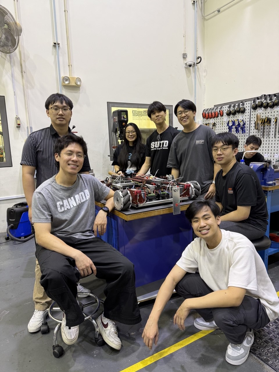
folder). Board designs by Kai Xiang & Heng Li (arm/wheel sensor side) and Bryan Lim (base).
Demos
Load test — ≥100 kg requirement load, two people on top
Mecanum base driving and strafing
Arm extension / flipper / release sequence
Clamped onto a trolley
(GitHub renders <video> tags in markdown; if your viewer doesn't, open the files under
docs/media/videos/.)
specs, gotchas, hardware references, runbooks, session history, media
Project history — what was tried and dropped
Kept because knowing what was attempted saves repeating it. None of the below
is part of the delivered machine.
Abandoned
What it was
Why it went
AS5600 wheel encoders
four magnetic encoders, one per wheel, for closed-loop speed
Never worked on the fabricated board: pin 1 of every 1×04 encoder header is unconnected, and all four parts share address 0x36 on a commoned bus. The sensors and shaft magnets are still physically mounted on the motors, unwired and undriven. docs/gotchas.md §13
TCA9548A / PCA9548A I²C mux
fitted to give the four encoders separate addresses
Went with the encoders. An external PCA9548-type mux overheated and failed with more than two AS5600 attached. The ToF sensors never needed it — they use XSHUT re-addressing. Board files kept at KiCad/PCA9548A Breakout/
Raspberry Pi 5 as main controller
Pi 5 driving two ESP32s over USB serial, with a link watchdog
The parser was written but Bluepad32 owns stdin, so it never ran. Operator control is the gamepad. docs/gotchas.md §6
Hardware E-stop input
a GPIO for an emergency-stop button
Discussed, never implemented. The red mushroom button on the robot is wired as an enable for the 12 V arm rail — docs/hardware/startup.md §1
Base-board clamp driver
BTS7960 clamp driven from the base ESP
Moved to the arm subsystem. The base pins remain kNoPin so the one-ESP firmware still compiles
Code for the encoders, the mux and the Pi was deleted on 2026-08-31 rather
than left to rot — git log --diff-filter=D recovers any of it. What was worth
keeping is the analysis of why each failed, which lives in
docs/gotchas.md and docs/hardware/.
Acknowledgements
Course 30.007 Engineering Design Innovation, SUTD; reviewed by Prof. Bradley Camburn and Prof. Wai Lee Chan
Firmware drafting and design-analysis support used AI tooling (Claude, Gemini), as disclosed in the PDR
An AMR-style under-ride platform that drives beneath a textile trolley, uses upward-facing time-of-flight sensors to confirm it is under the trolley and centred, clamps onto the underside, and then moves the trolley.
An AMR-style under-ride platform that drives beneath a textile trolley, uses upward-facing time-of-flight sensors to confirm it is under the trolley and centred, clamps onto the underside, and then moves the trolley.
It measures 42.8 × 33.8 mm and has 2 copper layers, 1.6 mm thick.
What parts does the Driver PCB use?
16 parts. The full list of its parts is on this page, with links to each part's symbol and footprint where PCBKit's library has them.
Where can I download the Driver PCB KiCad files?
From the lnpanini/Falali repository on GitHub, at the commit this page was made from: the board is KiCad/Driver PCB/Driver PCB.kicad_pcb and its schematic KiCad/Arm Subsystem PCB/Arm Subsystem PCB.kicad_sch. PCBKit opens the board in the browser, with nothing to install.
Can I use the Driver PCB design in my own project?
Its repository states no licence, so its author keeps all rights: ask lnpanini before reusing the design.