

4 layers56.1 × 57.1 mm
MCL86jr
MicroCoreLabs/Projects
Ted Fried's MicroCore Labs Projects - FPGA CPU cores and emulators for the 8088, 8086, 8051, 6502, 68000, Z80, Risc-V, and also Typewriter and EPROM Emulator projects.
66 parts534

 lmcapacho/ESP32_LogicAnalyzer28
Low-cost logic analyzer using ESP32 for fast digital signal debugging
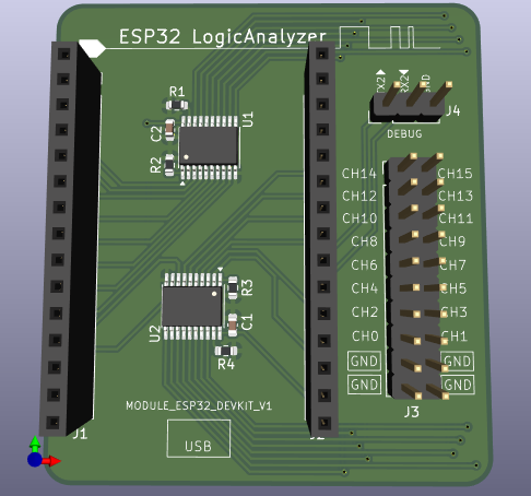
ESP32 LogicAnalyzer is an open-source printed circuit board by lmcapacho, from the lmcapacho/ESP32_LogicAnalyzer repository on GitHub, published under the GPL-3.0 licence. It is a 2-layer board of 48 × 53.3 mm with 12 parts on 48 nets, routed with 184 tracks and 17 vias.
It is built around the SN74LVC245APW. Its parts include 4 resistors, 4 connectors, 2 capacitors and 2 ICs. It belongs with the sensors and measurement boards and the ESP32 boards of this library.

A SUMP compatible 16Bit Logic Analyzer for ESP32 MCUs.
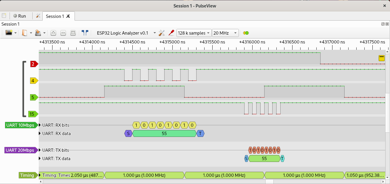
| Environment | Status | Details |
|---|---|---|
| PlatformIO | ✅ | Tested with platform-espressif32@6.11.0 |
| Arduino IDE | ✅ | Tested with Arduino-ESP32 core 3.3.7 |
esp32 by Espressif Systems).ESP32_LogicAnalyzer/ESP32_LogicAnalyzer.ino.ESP32 Dev Module).3.3.7.Important: If you're using UART0 for OLS communication, set Core Debug Level = None in the Arduino IDE before compiling, especially for captures above 10 MHz.
Open PulseView with:
pulseview -D -d ols:conn=/dev/ttyUSB0::serialcomm=921600/8n1Or from the GUI, connect the device and select Openbench Logic Sniffer & SUMP compatibles (ols).
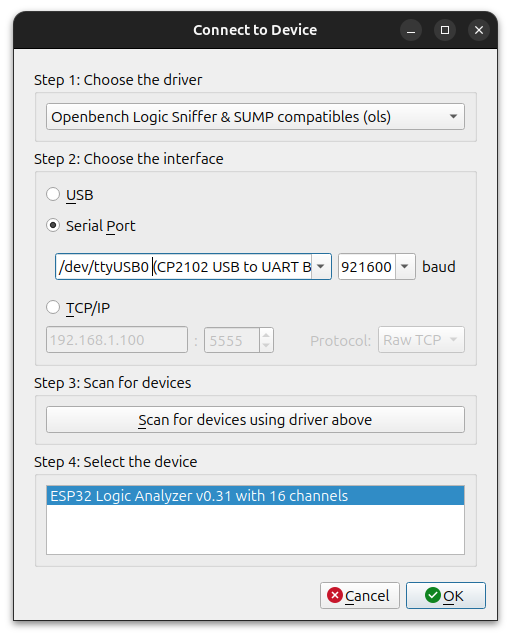
RLE can be enabled in Device configuration dialog:
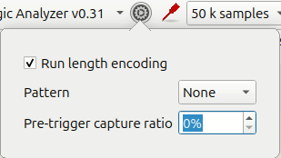
For more details, see the PulseView documentation.
| Pin | Connection |
|---|---|
| clk_in | GPIO23 (connect to clk_out) |
| clk_out | GPIO22 (connect to clk_in) |
| Ground | Connect the target device's GND to the ESP32 GND |
| Channels | CH15 - CH0 (connect your signals here) |
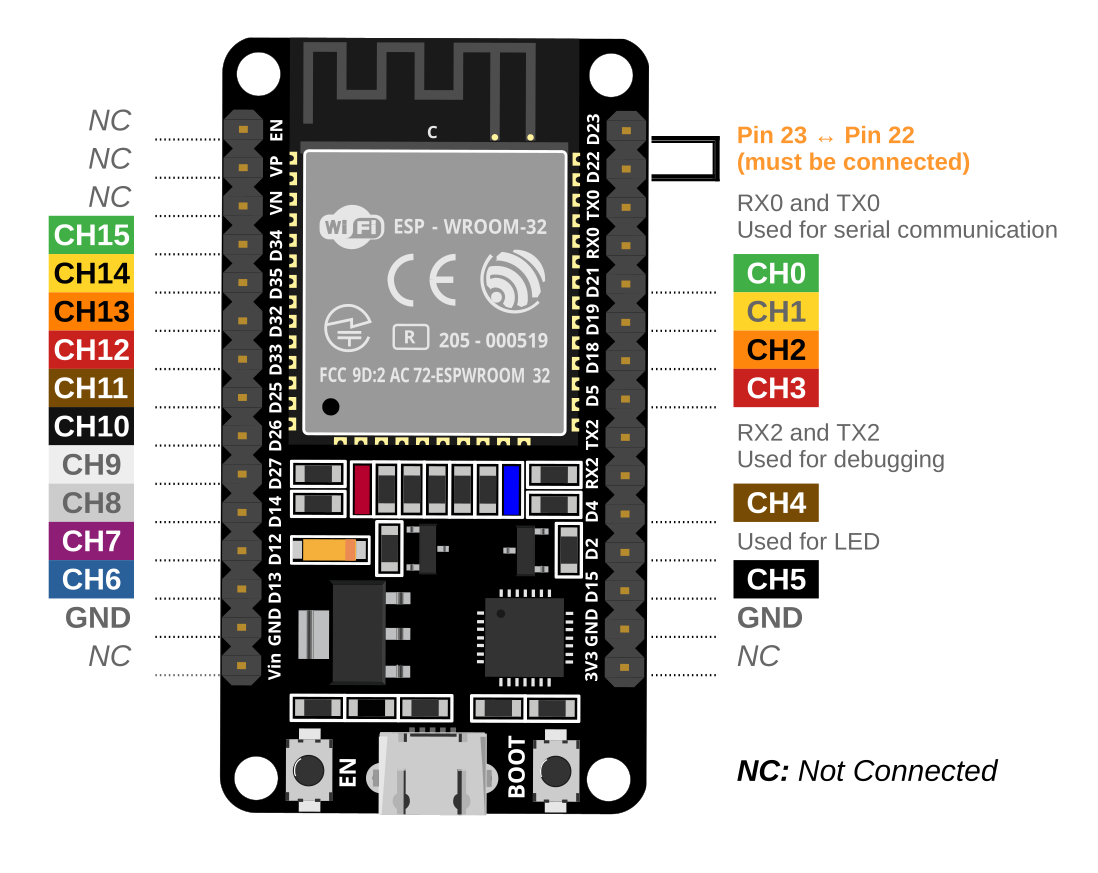
⚠️ Warning: GPIO23 is used for I2S input clock and GPIO22 for LEDC output clock.
Do not use these pins for general I/O. If needed, change them in the code and rewire accordingly.
This project includes a custom PCB designed in KiCad 9 to connect the ESP32 DevKitC V1 with logic analyzer channels and level shifters.
All hardware-related files are located in the hardware/ folder and include:
.kicad_pro, .kicad_sch, .kicad_pcb)BOM.xlsx) and CPL (CPL1.xlsx) for assemblyhardware/gerbers/) for PCB fabrication⚠️ The design is currently under validation. Use at your own risk until physical tests are completed.
This project is a fork of ESP32_LogicAnalyzer, created by Erdem U. Altinyurt.
This project uses code from:
This project is licensed under the GPL 3.0 License. See the LICENSE file for details.
| Qty | Value | Footprint | References |
|---|---|---|---|
| 4 | 10K | Resistor_SMD:R_0603_1608Metric | R1, R2, R3, R4 |
| 2 | 100n | Capacitor_SMD:C_0603_1608Metric | C1, C2 |
| 2 | Conn_01x15 | Connector_PinSocket_2.54mm:PinSocket_1x15_P2.54mm_Vertical | J1, J2 |
| 2 | SN74LVC245APW | Package_SO:TSSOP-20_4.4x6.5mm_P0.65mm | U1, U2 |
| 1 | CHANNELS | Connector_PinHeader_2.54mm:PinHeader_2x10_P2.54mm_Vertical | J3 |
| 1 | DEBUG | Connector_PinHeader_2.54mm:PinHeader_1x03_P2.54mm_Vertical | J4 |
MicroCoreLabs/Projects
Ted Fried's MicroCore Labs Projects - FPGA CPU cores and emulators for the 8088, 8086, 8051, 6502, 68000, Z80, Risc-V, and also Typewriter and EPROM Emulator projects.

fliperama86/neopico-hd
Digital video and audio capture with HDMI output for Neo Geo MVS arcade hardware using Raspberry Pi Pico 2

ceteras/PicoLVDS
Tested with B089AW01-V.0 and HSD089IFW1-A00-V1.0 on a breadboard. I'm sure it will work with other displays from old netbooks.

gianluca-rainis/Z80DevBoard
An advanced development board for the Z80 microprocessor, powered by an RP2040.

KungfuPancake/longboi
Possibly the longest controller board to control the BoxTurtle AFC


BlackPancakes/RP2040-Logic-Analyzer
An open-source, high-speed, multi-channel logic analyzer based on the popular Raspberry Pi RP2040 microcontroller. The board was designed in KiCad with a strong focus on signal integrity and miniaturization.

DrJonEA/RP2040QuadMotorController
RP2040Zero and AT8236 Based Quad Motor Controller
It measures 48 × 53.3 mm and has 2 copper layers, 1.6 mm thick.
12 parts, built around the SN74LVC245APW. The full list of its parts is on this page, with links to each part's symbol and footprint where PCBKit's library has them.
From the lmcapacho/ESP32_LogicAnalyzer repository on GitHub, at the commit this page was made from: the board is hardware/ESP32_LogicAnalyzer.kicad_pcb and its schematic hardware/ESP32_LogicAnalyzer.kicad_sch. PCBKit opens the board in the browser, with nothing to install.
Its repository publishes it under the GPL-3.0 licence: you may reuse it on that licence's terms (keep the author's notice, and for a copyleft licence share your changes alike).