2 layers68.6 × 53.3 mm
Arduino UNO click shield
michpro/mikroBUS
Collection of add-on boards in mikroBUS™ standard
24 parts5CERN-OHL-P-2.0

 llatva/pupill321
pu(rple)pill32 -- An indie evalboard for PY32F030F1xP6
Pupill32 is an open-source printed circuit board by llatva, from the llatva/pupill32 repository on GitHub, published under the CERN-OHL-W-2.0 licence. It is a 2-layer board of 52.1 × 27.9 mm with 54 parts on 43 nets, routed with 439 tracks and 148 vias.
It is built around the PY32F030F18P6TU, CH340N and AMS1117-3.3, with the SRV05-4 among its other parts. Its parts include 18 capacitors, 12 resistors, 4 ICs, 4 connectors and 2 diodes.


RevA had some glitches, please refer to changelog in the revB schematic or below. RevB tested to be functional, and can be flash-programmed over USB (see bootloader access below).
**) In that case, if you don't need pull-ups for your signals, do not populate R11-R12.
USB UART is connected to PA2/PA3 (TX/RX). To access bootloader (e.g. puyaisp.py /1/, USB-to-serial), either
OR
/1/ [https://github.com/wagiminator/MCU-Flash-Tools]
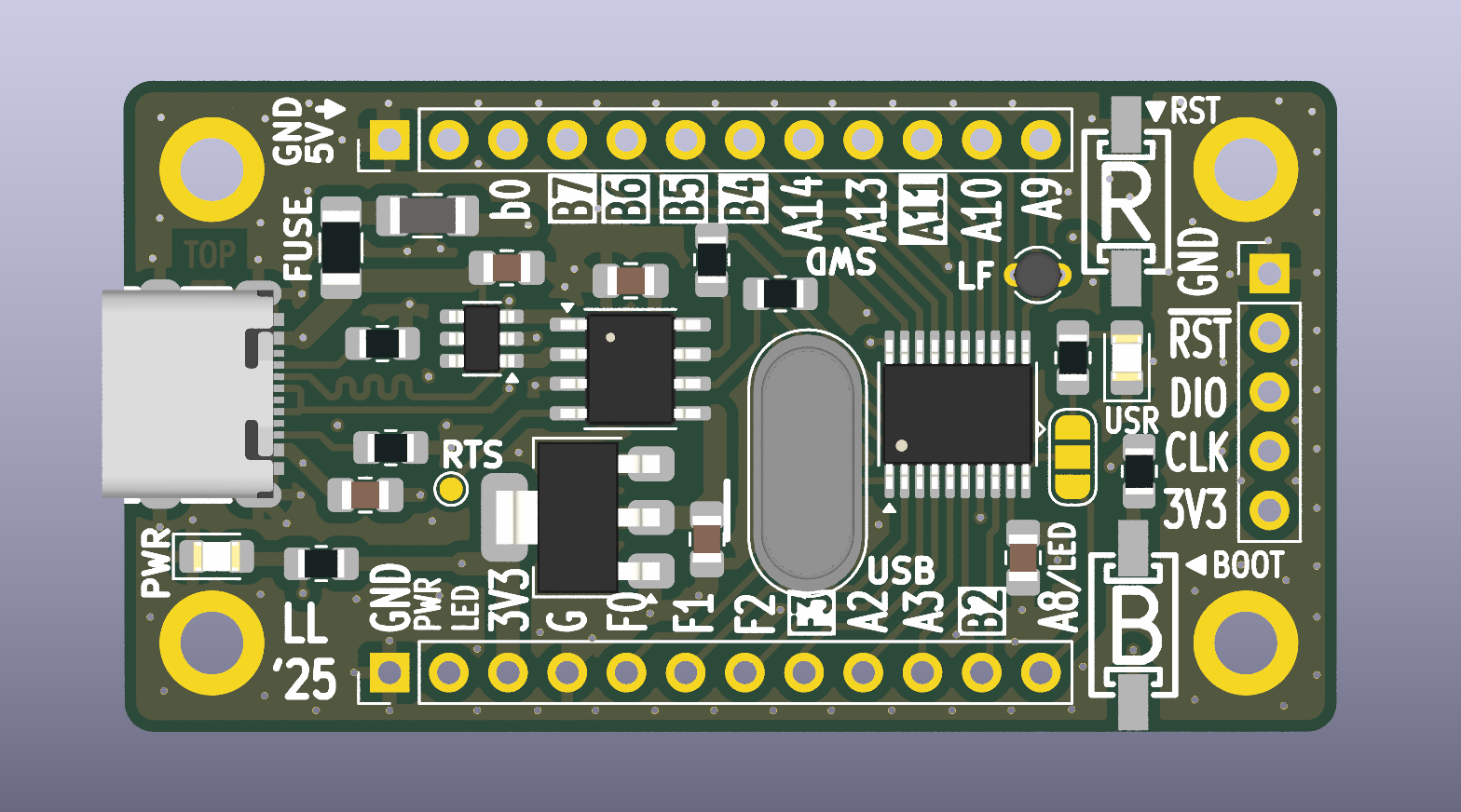
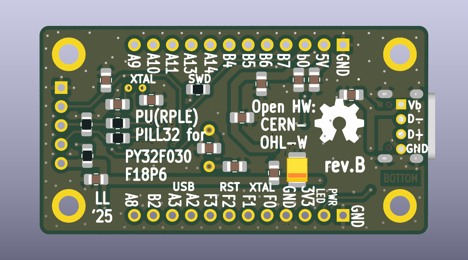
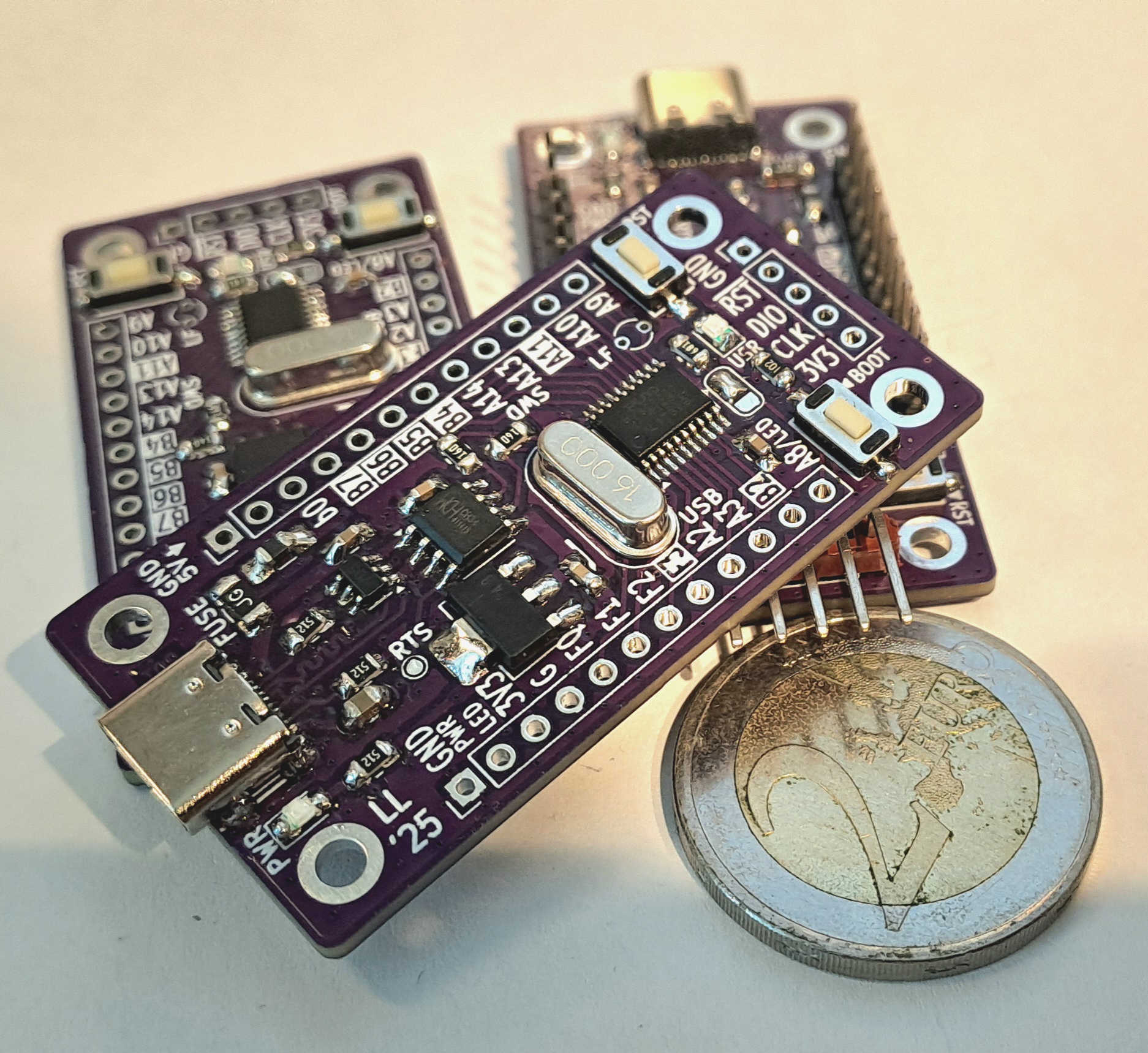
This project is no way affiliated with Puya Semiconductor or any other commercial body. This is an indie evaluation board designed and built by a hobbyist. You may use this open hardware design, at your own risk, according to its license conditions, see the following chapter.
/2/ J. Carlson: The cheapest flash microcontroller you can buy is actually an ARM CORTEX-M0+
This board is licensed under CERN Open Hardware License, version 2, CERN-OHL-W (weakly reciprocal).
Please refer to LICENSE file for more information.
| Qty | Value | Footprint | References |
|---|---|---|---|
| 8 | 100nF | Capacitor_SMD:C_0805_2012Metric_Pad1.18x1.45mm_HandSolder | C3, C4, C5, C10, C11, C12, C15, C19 |
| 4 | 12p | Capacitor_SMD:C_0805_2012Metric_Pad1.18x1.45mm_HandSolder | C8, C13, C17, C18 |
| 4 | MountingHole | MountingHole:MountingHole_2.7mm_M2.5_ISO7380_Pad | H1, H2, H3, H4 |
| 3 | 10k | Resistor_SMD:R_0805_2012Metric_Pad1.20x1.40mm_HandSolder | R1, R11, R12 |
| 3 | 10uF | Capacitor_SMD:C_0805_2012Metric_Pad1.18x1.45mm_HandSolder | C6, C9, C14 |
| 3 | 5k1 | Resistor_SMD:R_0805_2012Metric_Pad1.20x1.40mm_HandSolder | R2, R3, R4 |
| 2 | 0R | Resistor_SMD:R_0805_2012Metric_Pad1.20x1.40mm_HandSolder | R5, R6 |
| 2 | 1k | Resistor_SMD:R_0805_2012Metric_Pad1.20x1.40mm_HandSolder | R7, R8 |
| 2 | 1uF | Capacitor_SMD:C_0805_2012Metric_Pad1.18x1.45mm_HandSolder | C1, C7 |
| 2 | 22R | Resistor_SMD:R_0805_2012Metric_Pad1.20x1.40mm_HandSolder | R9, R10 |
| 1 | 0.8A | Fuse:Fuse_1206_3216Metric_Pad1.42x1.75mm_HandSolder | F1 |
| 1 | 12M | Crystal:Crystal_HC49-4H_Vertical | Y2 |
| 1 | 22uF | Capacitor_Tantalum_SMD:CP_EIA-3528-21_Kemet-B_Pad1.50x2.35mm_HandSolder | C20 |
| 1 | 32.768 kHz | Crystal:Crystal_Round_D2.0mm_Vertical | Y1 |
| 1 | AMS1117-3.3 | Package_TO_SOT_SMD:SOT-223-3_TabPin2 | U4 |
| 1 | BOOT_BTN | pupill32:SW-SMD_L6.0-W3.5-LS8.2 | SW2 |
| 1 | CH340N | Package_SO:SOP-8_3.9x4.9mm_P1.27mm | U3 |
| 1 | HeaderL | Connector_PinHeader_2.54mm:PinHeader_1x12_P2.54mm_Vertical | J2 |
| 1 | HeaderR | Connector_PinHeader_2.54mm:PinHeader_1x12_P2.54mm_Vertical | J1 |
| 1 | LED-G | LED_SMD:LED_0805_2012Metric_Pad1.15x1.40mm_HandSolder | D2 |
| 1 | LED-R | LED_SMD:LED_0805_2012Metric_Pad1.15x1.40mm_HandSolder | D3 |
| 1 | OSHW-Symbol_6.7x6mm_SilkScreen | Symbol:OSHW-Symbol_6.7x6mm_SilkScreen | OHW |
| 1 | PA8_SEL | Jumper:SolderJumper-3_P1.3mm_Open_RoundedPad1.0x1.5mm | JP2 |
| 1 | PY32F030F18P6 | Package_SO:TSSOP-20_4.4x6.5mm_P0.65mm | U2 |
| 1 | RST_BTN | pupill32:SW-SMD_L6.0-W3.5-LS8.2 | SW1 |
| 1 | RTSn | TestPoint:TestPoint_Pad_D1.0mm | TP1 |
| 1 | SRV05-4 | Package_TO_SOT_SMD:SOT-23-6 | U1 |
| 1 | SWD_HEADER | Connector_PinHeader_2.54mm:PinHeader_1x05_P2.54mm_Vertical | J4 |
| 1 | TYPE-C 16PIN 2MD(073) | pupill32:USB-C-SMD_TYPE-C-6PIN-2MD-073 | USB1 |
| 1 | USB_PINS | Connector_PinHeader_2.00mm:PinHeader_1x04_P2.00mm_Vertical | J3 |
| 1 | ~ | Inductor_SMD:L_1206_3216Metric_Pad1.42x1.75mm_HandSolder | FB1 |
It measures 52.1 × 27.9 mm and has 2 copper layers, 1.6 mm thick.
54 parts, built around the PY32F030F18P6TU, CH340N, AMS1117-3.3 and SRV05-4. The full list of its parts is on this page, with links to each part's symbol and footprint where PCBKit's library has them.
From the llatva/pupill32 repository on GitHub, at the commit this page was made from: the board is pupill32.kicad_pcb and its schematic pupill32.kicad_sch. PCBKit opens the board in the browser, with nothing to install.
Its repository publishes it under the CERN-OHL-W-2.0 licence: you may reuse it on that licence's terms (keep the author's notice, and for a copyleft licence share your changes alike).
michpro/mikroBUS
Collection of add-on boards in mikroBUS™ standard

Haimana/MAIANA_BLUE
Firmware and hardware materials for the MAIANA-class AIS transponder ecosystem. The design builds on the open MAIANA project (GPL v3, Peter Antypas).

OpenLogicEFI/Hardware
Hardware is based off an open source project called Speeduino by Josh Stewart.

rolandvs/ais_transponder
A real, functioning low-power AIS transponder (class B)

gili-yankovitch/SwordOfSecrets
To solve the challenge you will need to discover a series of flags, hidden inside the sword. Each one will help you unlock the next step in the challenge, to finally reveal the ultimate secret the sword holds.


tjclement/ecsc23-badge
This repo contains the hardware designs and firmware developed for the ECSC23 hardware challenge by Curious Supplies.

xuejun7777/Comprehensive-Design-and-Practice-Project-A---Digital-Thermometer-Based-on-NTC
综合设计与实践A项目-基于NTC的数字温度计