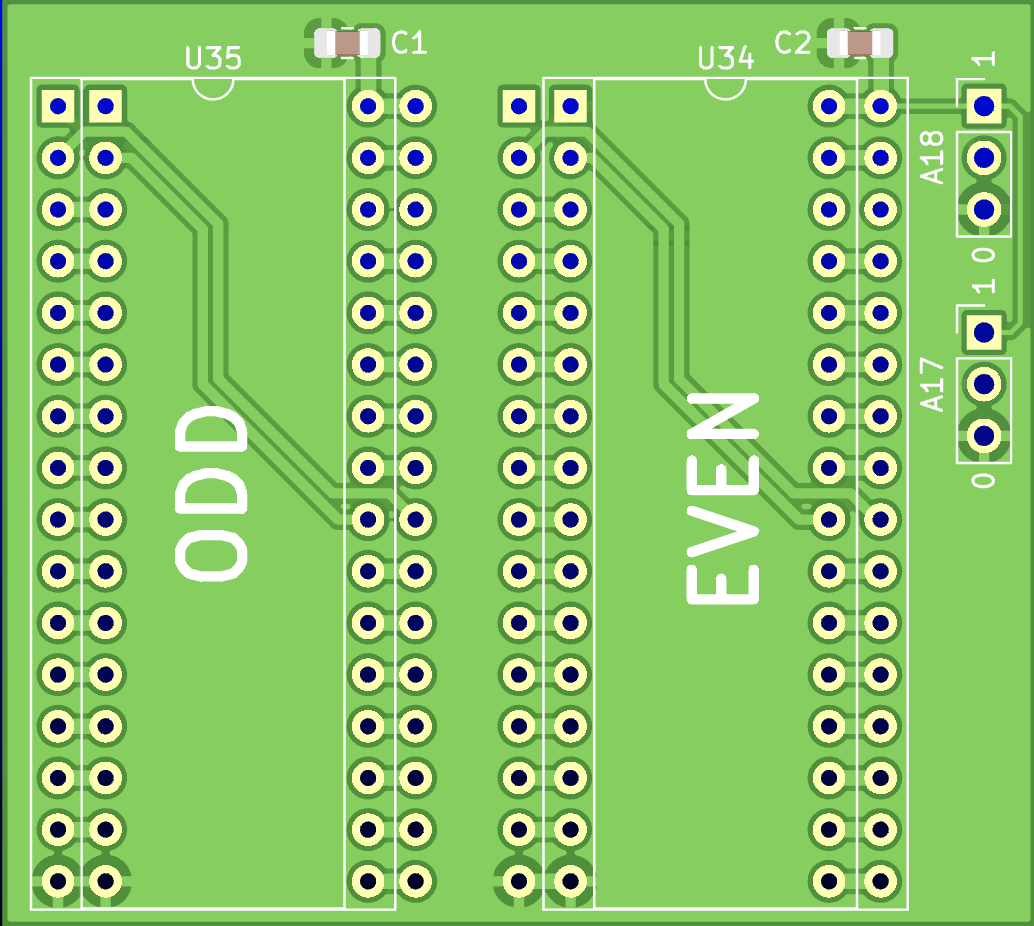
2 layers50.8 × 45.6 mm
Cdtv ext flash
LIV2/Bits-and-bobs
This work is licensed under a [Creative Commons Attribution-ShareAlike 4.0 International License][cc-by-sa].
8 parts4

 LIV2/Bits-and-bobs4
This work is licensed under a [Creative Commons Attribution-ShareAlike 4.0 International License][cc-by-sa].
ZorroDebug is an open-source printed circuit board by LIV2, from the LIV2/Bits-and-bobs repository on GitHub. It is a 2-layer board of 129.5 × 51 mm with 3 parts on 83 nets, routed with 391 tracks and 0 vias.

This work is licensed under a Creative Commons Attribution-ShareAlike 4.0 International License.

| Qty | Value | Footprint | References |
|---|---|---|---|
| 1 | Zorro2 | Zorro:Zorro2-Connector-Edgemount | CON2 |
| 1 | Zorro2 | Zorro:Zorro2-Connector | CON3 |
| 1 | Zorro2 | Zorro:Zorro2-CardEdge | CON1 |
LIV2/Bits-and-bobs
This work is licensed under a [Creative Commons Attribution-ShareAlike 4.0 International License][cc-by-sa].


hzeller/rpi-rgb-led-matrix
Controlling up to three chains of 64x64, 32x32, 16x32 or similar RGB LED displays using Raspberry Pi GPIO


atopile/atopile
Design circuit boards with code! ✨ Get software-like design reuse 🚀, validation, version control and collaboration in hardware; starting with electronics ⚡️


hackclub/sprig
🍃 Learn to code by making games in a JavaScript web-based game editor.
It measures 129.5 × 51 mm and has 2 copper layers, 1.6 mm thick.
3 parts. The full list of its parts is on this page, with links to each part's symbol and footprint where PCBKit's library has them.
From the LIV2/Bits-and-bobs repository on GitHub, at the commit this page was made from: the board is ZorroDebug/ZorroDebug.kicad_pcb and its schematic CDTV-Ext-FLASH/cdtv-ext-flash.kicad_sch. PCBKit opens the board in the browser, with nothing to install.
Its repository states no licence, so its author keeps all rights: ask LIV2 before reusing the design.