4 layers100 × 47.4 mm

 linuxplayground/6502-retro
A 6502 Backplane design.
6502-retro is an open-source printed circuit board by linuxplayground, from the linuxplayground/6502-retro repository on GitHub. It is a 4-layer board of 100 × 100 mm with 36 parts on 72 nets, routed with 832 tracks and 194 vias.
It is built around the DS1813-5+ and SN74HC08N. Its parts include 11 capacitors, 8 resistors, 7 ICs, 5 connectors and 2 crystals. It belongs with the retro computing and games boards of this library.

Inspired by the Z80-Retro! see: https://github.com/z80-retro I decided to see if I could put together a small 6502 based project with a similar design philosphy. The main goals of the project are:
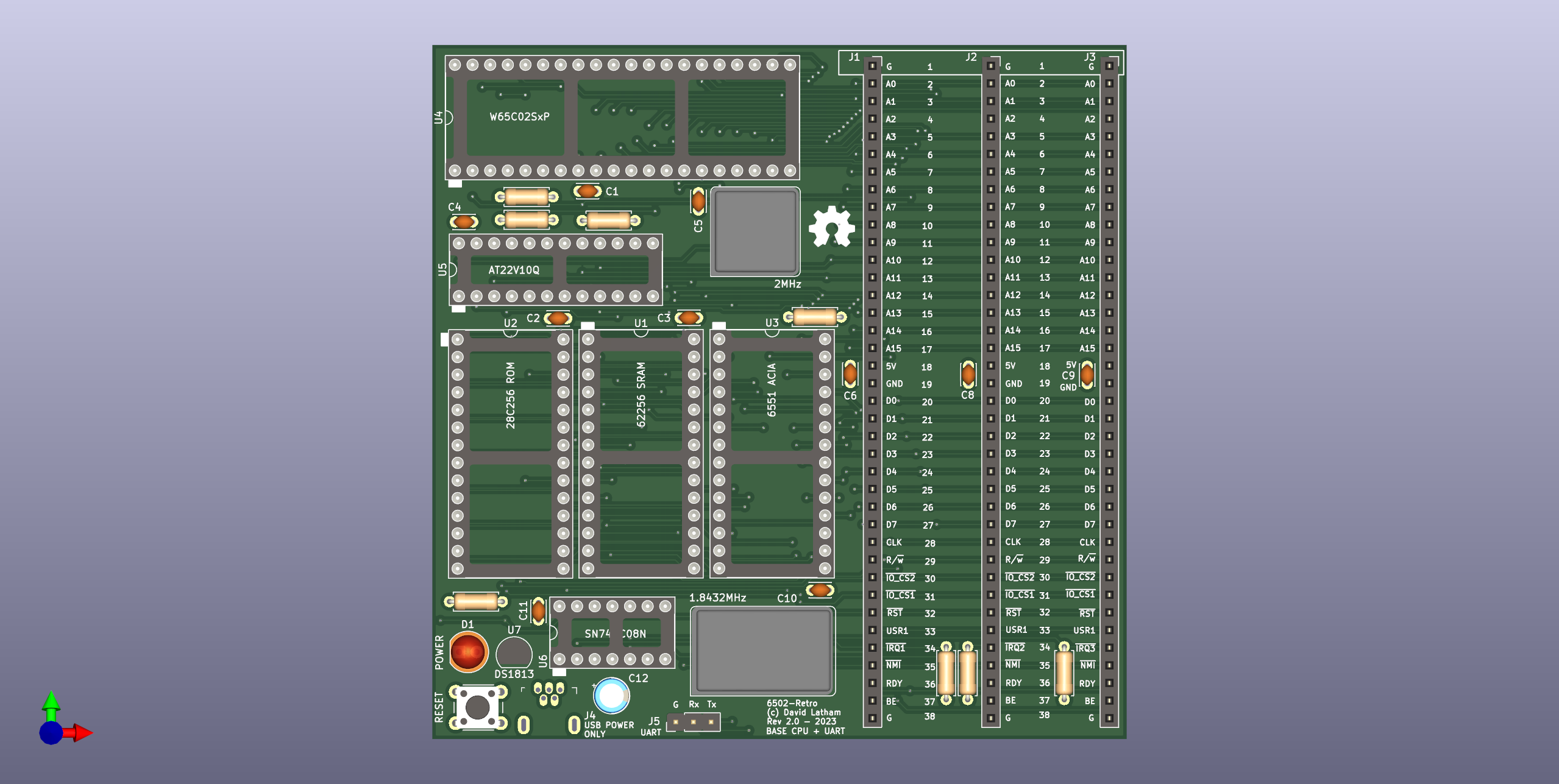
You can find the hardware schematic and gerber files for the base board in hardware/6502-retro.
This project contains two expansion boards.
One of the expansion slots (J1) is too close to the BAUD RATE Oscilator on the base board. It can be used for manual jumper wires maybe, but I would not risk putting a card in there as the solder joints on the back of the card will short against the metal oscilator can for the baud rate clock.
The F18A from dnotq is mounted with some glue logic on an expansion board. It provides all the same features as the TMS9918A VDP along with some additional enhancments that can be accessed in software.
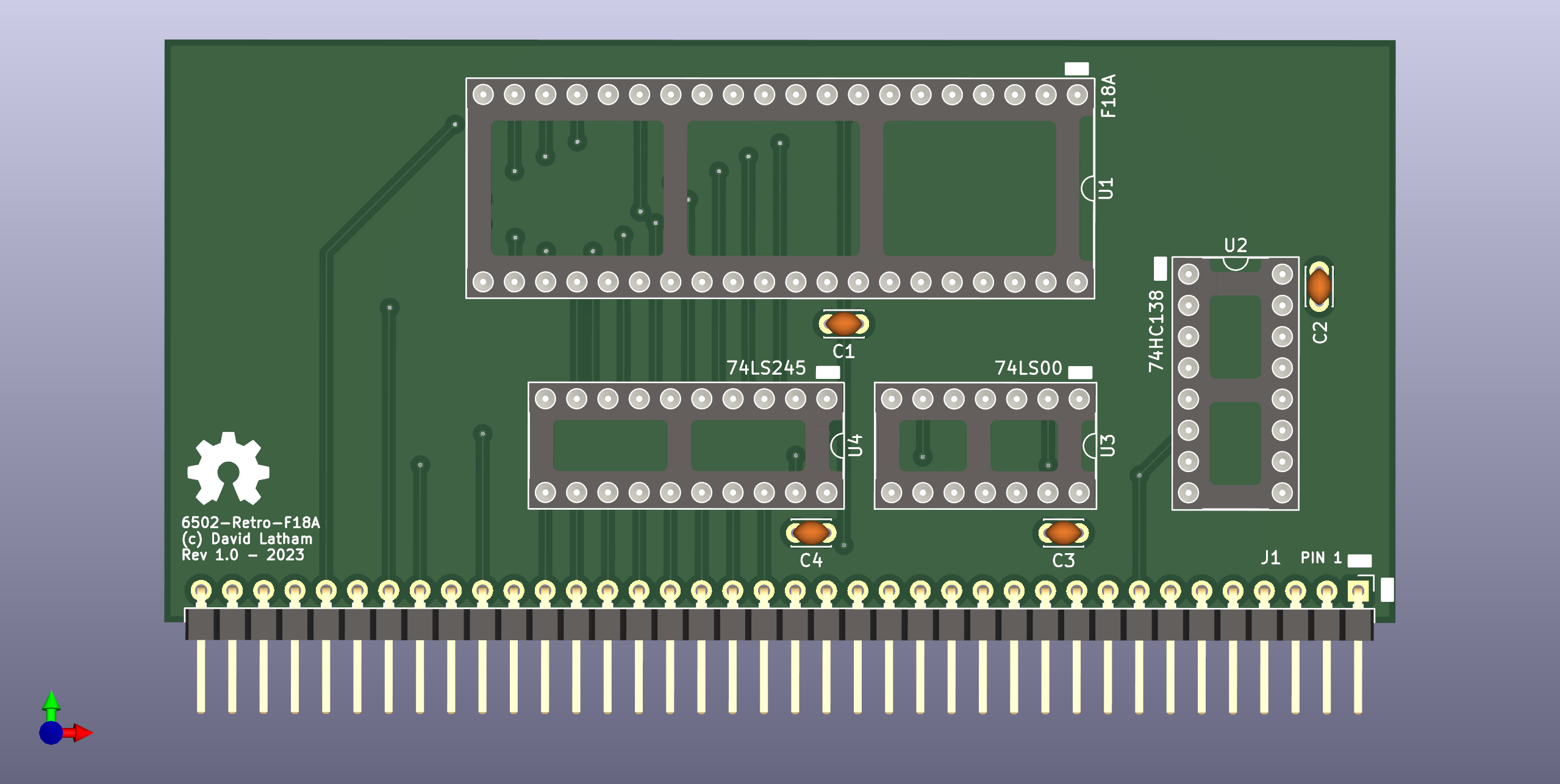
You can find the hardware schematic here.
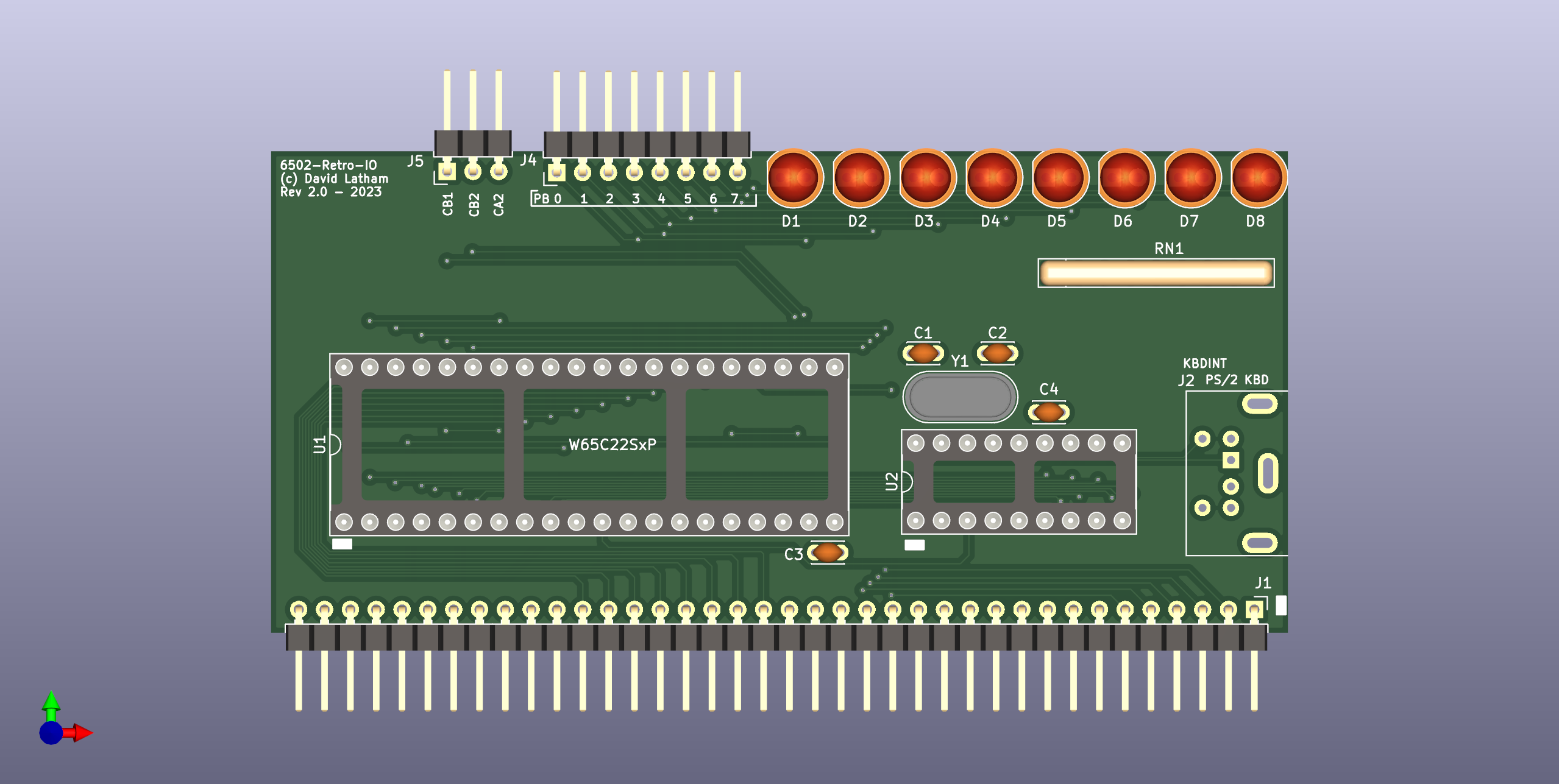
You can find the hardware schematic here.
Note: PS/2 Support is designed for the PERIBOARD-409 P - Mini PS/2 keyboard
This board has a "sign-on" routine that's handled in the PIC16F628A microcontroller. The code for the MCU is included here
The more generic / standard PS/2 Keyboards will require the MCU code to be altered.
The memory map is given by an AT22v10Q PLD which provides ranges in the table below. These values are also defined in 6502-retro-rom.cfg
| Range | Description | Size | Decoder Pins | Comments |
|---|---|---|---|---|
| 0000-00FF | Zero Page | 0x100 | ||
| 0100-0200 | Stack | 0x100 | ||
| 0200-0FFF | SYSRAM | 0xE00 | ||
| 1000-7EFF | RAM | 0x6F00 | ||
| 7F00-7F10 | UNMAPPED | 0x16 | ||
| 7F10-7F1F | FREE | 0x16 | IOCS1 + A4 | IOCS1 is clock qualified |
| 7F20-7F2F | ACIA | 0x16 | IOCS1 + A5 | |
| 7F30-7F3F | UNMAPPED | 0x16 | ||
| 7F40-7F4F | F18A / TMS9918A | 0x16 | IOCS1 + A6 | |
| 7F50-7F8F | UNAMPPED | 0x64 | ||
| 7F90-7F90 | VIA | 0x16 | IOCS2 + A4 | IOCS2 is not clock qualified |
| 7FA0-7FAF | FREE | 0x16 | IOCS2 + A5 | |
| 7FB0-7FBF | UMAPPED | 0x16 | ||
| 7FC0-7FCF | FREE | 0x16 | IOCS2 + A6 | |
| 7FD0-7FEF | UNMAPPED | 0x64 |
See the PLD Code for the WinCUPL design file.
| Qty | Value | Footprint | References |
|---|---|---|---|
| 10 | 0.1uF | Capacitor_THT:C_Disc_D3.0mm_W2.0mm_P2.50mm | C1, C2, C3, C4, C5, C6, C8, C9, C10, C11 |
| 7 | 3.9K | Resistor_THT:R_Axial_DIN0207_L6.3mm_D2.5mm_P7.62mm_Horizontal | R2, R4, R5, R6, R8, R9, R10 |
| 1 | 0548190519 | digikey-footprints:USB_Mini_B_Female_548190519 | J4 |
| 1 | 1.8432MHz | Oscillator:Oscillator_DIP-14 | X2 |
| 1 | 10uF | Capacitor_THT:CP_Radial_D5.0mm_P2.50mm | C12 |
| 1 | 220 | Resistor_THT:R_Axial_DIN0207_L6.3mm_D2.5mm_P7.62mm_Horizontal | R7 |
| 1 | 28C256 ROM | Package_DIP:DIP-28_W15.24mm_Socket | U2 |
| 1 | 2MHz | Oscillator:Oscillator_DIP-8 | X1 |
| 1 | 62256 SRAM | Package_DIP:DIP-28_W15.24mm_Socket | U1 |
| 1 | 6551 ACIA | Package_DIP:DIP-28_W15.24mm_Socket | U3 |
| 1 | AT22V10Q | Package_DIP:DIP-24_W7.62mm_Socket | U5 |
| 1 | Conn_01x03_Male | Connector_PinHeader_2.54mm:PinHeader_1x03_P2.54mm_Vertical | J5 |
| 1 | DS1813 | Package_TO_SOT_THT:TO-92_Inline | U7 |
| 1 | POWER | LED_THT:LED_D5.0mm | D1 |
| 1 | RESET | Button_Switch_THT:SW_PUSH_6mm_H5mm | SW1 |
| 1 | SLOT 1 | Connector_PinSocket_2.54mm:PinSocket_1x38_P2.54mm_Vertical | J1 |
| 1 | SLOT 2 | Connector_PinSocket_2.54mm:PinSocket_1x38_P2.54mm_Vertical | J2 |
| 1 | SLOT 3 | Connector_PinSocket_2.54mm:PinSocket_1x38_P2.54mm_Vertical | J3 |
| 1 | SN74HC08N | Package_DIP:DIP-14_W7.62mm_Socket | U6 |
| 1 | W65C02SxP | Package_DIP:DIP-40_W15.24mm_Socket | U4 |
The 35 most common of 36 parts.


dsorensen228/sherman
Desktop robot project with C++ personality and display runtimes, Python hardware services, Pico 2 firmware, and PCB and enclosure design.

blkhurst/kicad-usb-c
This USB-C Powered AND Gate is the first PCB I have designed using KiCad, and serves as a proof of concept for integrating USB-C power into future projects. The design includes:


PhdWizards/4-Bit-Discrete-Transistor-Adder
The core 4-bit binary adder is implemented entirely using discrete transistor-resistor logic. The resulting 5-bit binary value is converted to BCD using 74HC-series logic and displayed on two 7-segment displays.


semteXKG/fiesta-hardware
idf.py.exe -p COM4 -DPRIMARY=1 -DFORD=1 build flash monitor
It measures 100 × 100 mm and has 4 copper layers, 1.6 mm thick.
36 parts, built around the DS1813-5+ and SN74HC08N. The full list of its parts is on this page, with links to each part's symbol and footprint where PCBKit's library has them.
From the linuxplayground/6502-retro repository on GitHub, at the commit this page was made from: the board is hardware/6502-retro/6502-retro.kicad_pcb and its schematic hardware/6502-retro-f18a/6502-retro-f18a.kicad_sch. PCBKit opens the board in the browser, with nothing to install.
Its repository states no licence, so its author keeps all rights: ask linuxplayground before reusing the design.