
2 layers26 × 30 mm
Microcontroller
FrameworkComputer/ExpansionCards
Reference designs and documentation to create Expansion Cards for the Framework Laptop
34 parts1.1kCC-BY-4.0

 linusnc183/ball-tracking-robot
A two-wheeled robot that visually tracks and follows a red ball. A Raspberry Pi handles vision (Picamera2 + OpenCV) and sends drive commands over UART to a custom STM32-based motor controller PCB, which closes the loop…
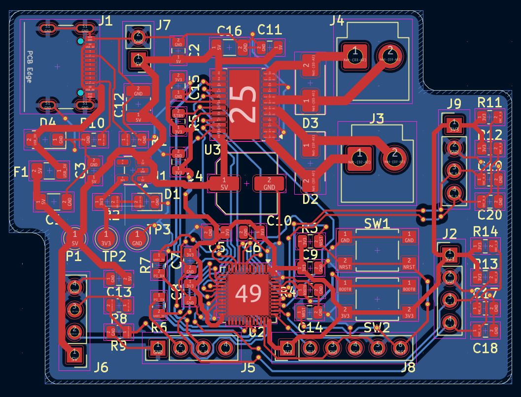
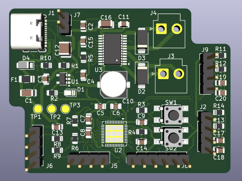
Ball Tracking Robot Controller is an open-source printed circuit board by linusnc183, from the linusnc183/ball-tracking-robot repository on GitHub. It is a 2-layer board of 56.5 × 42 mm with 56 parts on 60 nets, routed with 795 tracks and 76 vias.
It is built around the AP2112K-3.3. Its parts include 20 capacitors, 14 resistors, 9 connectors, 4 diodes and 3 ICs. It belongs with the robots and motor control boards and the STM32 boards of this library.
A two-wheeled robot that visually tracks and follows a red ball. A Raspberry Pi handles vision (Picamera2 + OpenCV) and sends drive commands over UART to a custom STM32-based motor controller PCB, which closes the loop with encoder feedback and PID.
I designed the controller PCB from scratch in KiCad and wrote the embedded firmware in C (STM32CubeIDE, HAL).
Skills demonstrated: PCB design (KiCad) · embedded C / STM32 HAL · real-time control loops (PID) · analog/digital circuit design (power regulation, signal protection) · computer vision (OpenCV) · serial communication protocol design
https://github.com/user-attachments/assets/ed4e9871-f768-4ec5-b8f6-aebbd3194bc8
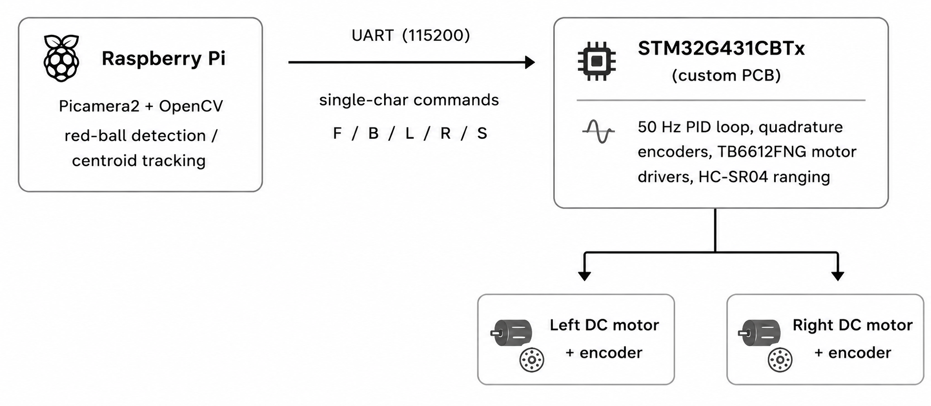
Why split the work this way: the Raspberry Pi handles the computationally heavy, non-deterministic side — image processing, ball detection, high-level navigation decisions. The STM32 handles the deterministic, real-time side — PWM generation, encoder feedback, PID control, and motor safety. Keeping them separate means a slow camera frame can never disturb the timing of the motor control loop.
Custom 2-layer controller PCB designed from scratch in KiCad 9 (schematic + layout), organized into hierarchical sheets by subsystem.
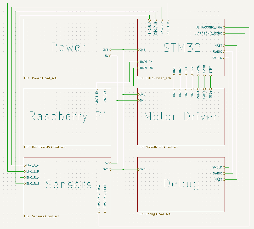
Power.kicad_sch)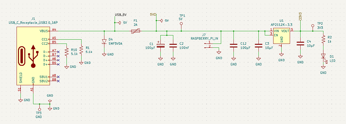
MotorDriver.kicad_sch)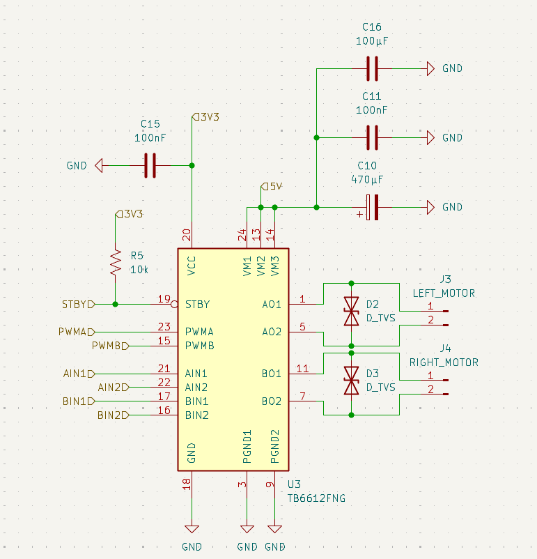
AIN1/AIN2/BIN1/BIN2 for direction and PWMA/PWMB (from TIM1 CH1/CH2) for speed, with STBY used to enable/disable the driver in firmware.Sensors.kicad_sch)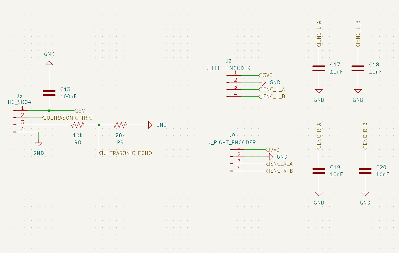
TRIG/ECHO connect directly to the STM32 (PA0/PA1). Since the HC-SR04's echo pin outputs a 5V logic level and the STM32 is 3.3V-tolerant, a resistive divider (20 kΩ/10 kΩ) steps the echo signal down to a safe ~3.3V before it reaches the MCU pin.STM32.kicad_sch)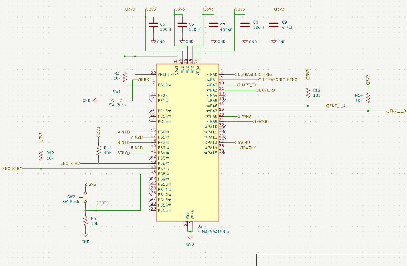
RaspberryPi.kicad_sch)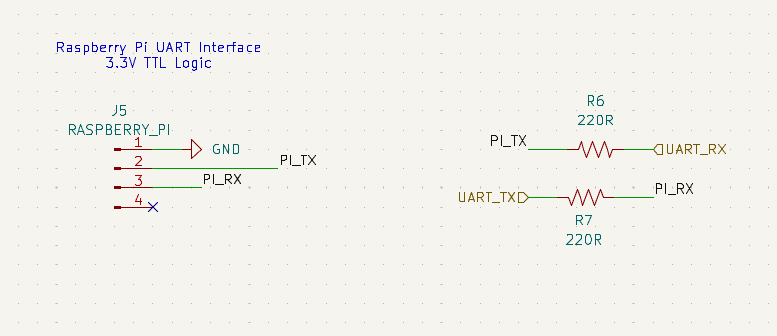
Debug.kicad_sch)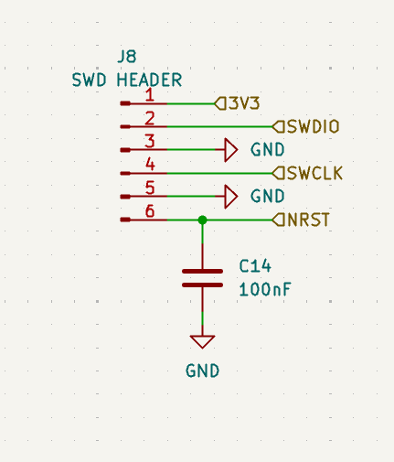
Key parts: STM32G431CBTx · TB6612FNG motor driver · HC-SR04 ultrasonic sensor · 2x quadrature encoders · AP2112K-3.3 LDO · USB-C power input · SMF5V0A TVS protection
| Module | Responsibility |
|---|---|
main.c | System init, 50 Hz control loop scheduling, 10 Hz ultrasonic scheduling |
motor.c/h | PWM + direction output to the TB6612FNG (TIM1 CH1/CH2, AIN/BIN GPIO) |
encoder.c/h | Reads TIM3/TIM4 in quadrature (TI12) encoder mode, converts counts to counts/sec |
pid.c/h | Per-wheel velocity PID with conditional-integration anti-windup |
uart_control.c/h | Parses single-character drive commands from the Pi over USART2 (interrupt-driven) |
ultrasonic.c/h | Software-timed HC-SR04 ranging using the DWT cycle counter for microsecond resolution |
CONTROL_LOOP_PERIOD_MS = 20): reads both encoders, runs independent PID controllers for the left/right wheel, and writes the resulting PWM + direction to the motor driver.Each wheel has an independent PID controller operating on measured wheel speed (encoder counts/sec) with output clamped to a ±1000 PWM range. Integral accumulation uses conditional integration: once the output saturates, the integral term stops accumulating unless the error is already pulling it back out of saturation. This prevents the classic windup overshoot where a saturated integrator keeps growing while the motor is already maxed out.
Wheel encoders are read using the STM32's hardware timer encoder mode (TIM_ENCODERMODE_TI12) on TIM3/TIM4, decoding both edges of both channels for full 4x quadrature resolution and reliable direction sensing, rather than software-polling the encoder pins.
The Pi sends single-byte commands over USART2 (interrupt-driven RX):
| Command | Action |
|---|---|
F | Forward |
B | Backward |
L | Turn left |
R | Turn right |
S | Stop |
If no byte arrives for 500 ms (e.g. the Pi crashes or the link drops), the firmware automatically zeroes both wheel targets and stops the robot — the robot doesn't require a "stop" command to fail safe.
The HC-SR04's echo line isn't wired to a timer input-capture pin, so pulse width is timed in software using the Cortex-M4's DWT cycle counter, giving microsecond-level resolution independent of the main loop's timing.
ball_tracking.py captures frames with Picamera2, finds the ball with OpenCV, and streams drive commands to the STM32 over the same UART protocol the firmware implements.
Detection: Frames are converted to HSV and thresholded for red across two hue ranges (red wraps around hue 0/180 in OpenCV's HSV space), combined into one mask, then cleaned up with erosion/dilation to remove noise. The largest contour's minimum enclosing circle gives the ball's center and apparent radius.
Decision logic: The ball's horizontal offset from frame-center picks a turn command first (turning takes priority so the robot centers on the ball before closing distance); once centered, the ball's apparent radius acts as a distance proxy — small radius drives forward, large radius backs up, and an in-between radius holds position.
Serial keepalive thread: The STM32 firmware stops the motors if it doesn't receive a UART byte within 500 ms. Rather than tying that timing to the camera's frame rate, SerialCommander runs a dedicated background thread that resends the current command every 150 ms on its own schedule — so a slow or dropped camera frame can never cause an unexpected stop or leave a stale command running longer than intended.
Debounced ball loss: Losing the ball for a single frame doesn't stop the robot; it keeps issuing the last command until the ball has been missing for a full second, avoiding jerky stops from momentary detection blips.
Run it with:
pip install picamera2 opencv-python pyserial numpy
python3 ball_tracking.py
Requires UART enabled via raspi-config (Interface Options → Serial Port) and, on Pi models where UART is routed through Bluetooth, dtoverlay=disable-bt in /boot/firmware/config.txt. Wiring: Pi GPIO14 (TX) → STM32 PA3 (RX), Pi GPIO15 (RX) → STM32 PA2 (TX), common ground — both sides are 3.3V logic, no level shifter needed.
Ball_Tracking_Robot/
├── README.md
├── .gitignore
│
├── hardware/                          # Custom PCB design files
│   └── PCB/
│       ├── KiCad/
│       │   ├── Ball_Tracking_Robot_Controller.kicad_pro
│       │   ├── Ball_Tracking_Robot_Controller.kicad_sch
│       │   ├── Ball_Tracking_Robot_Controller.kicad_pcb
│       │   ├── STM32.kicad_sch
│       │   ├── Power.kicad_sch
│       │   ├── MotorDriver.kicad_sch
│       │   ├── Sensors.kicad_sch
│       │   ├── RaspberryPi.kicad_sch
│       │   └── Debug.kicad_sch
│       ├── Gerbers/                   # Manufacturing files
│       └── BOM/
│
├── firmware/                          # STM32 embedded firmware (STM32CubeIDE project)
│   └── STM32CubeIDE/
│       ├── Core/
│       │   ├── Inc/                   # main.h, motor.h, encoder.h, pid.h,
│ │ │ # uart_control.h, ultrasonic.h, ...hardware/PCB/KiCad/Ball_Tracking_Robot_Controller.kicad_pro in KiCad 9.firmware/STM32CubeIDE directly as a project in STM32CubeIDE (targets the STM32G431CBTx).software/RaspberryPi/ball_tracking.py (see the Vision section above for setup details).Validation performed during hardware/firmware bring-up:
| Qty | Value | Footprint | References |
|---|---|---|---|
| 9 | 100nF | Capacitor_SMD:C_0805_2012Metric | C2, C5, C6, C7, C8, C11, C13, C14, C15 |
| 8 | 10k | Resistor_SMD:R_0805_2012Metric | R3, R4, R5, R8, R11, R12, R13, R14 |
| 4 | 10nF | Capacitor_SMD:C_0805_2012Metric | C17, C18, C19, C20 |
| 2 | 100μF | Capacitor_SMD:C_1206_3216Metric | C1, C16 |
| 2 | 10μF | Capacitor_SMD:C_0805_2012Metric | C3, C4 |
| 2 | 220R | Resistor_SMD:R_0805_2012Metric | R6, R7 |
| 2 | 5.1k | Resistor_SMD:R_0805_2012Metric | R1, R10 |
| 2 | D_TVS | Diode_SMD:D_SMA | D2, D3 |
| 2 | SW_Push | Button_Switch_SMD:SW_SPST_TL3305A | SW1, SW2 |
| 1 | 100μF | Capacitor_SMD:C_1210_3225Metric | C12 |
| 1 | 1k | Resistor_SMD:R_0805_2012Metric | R2 |
| 1 | 20k | Resistor_SMD:R_0805_2012Metric | R9 |
| 1 | 2A | Fuse:Fuse_1206_3216Metric | F1 |
| 1 | 3V3 | TestPoint:TestPoint_Pad_D2.0mm | TP2 |
| 1 | 4.7μF | Capacitor_SMD:C_0805_2012Metric | C9 |
| 1 | 470μF | Capacitor_SMD:C_Elec_6.3x5.8 | C10 |
| 1 | 5V | TestPoint:TestPoint_Pad_D2.0mm | TP1 |
| 1 | AP2112K-3.3 | Package_TO_SOT_SMD:SOT-23-5 | U1 |
| 1 | GND | TestPoint:TestPoint_Pad_D2.0mm | TP3 |
| 1 | HC_SR04 | Connector_PinHeader_2.54mm:PinHeader_1x04_P2.54mm_Vertical | J6 |
| 1 | J_LEFT_ENCODER | Connector_PinHeader_2.54mm:PinHeader_1x04_P2.54mm_Vertical | J2 |
| 1 | J_RIGHT_ENCODER | Connector_PinHeader_2.54mm:PinHeader_1x04_P2.54mm_Vertical | J9 |
| 1 | LED | LED_SMD:LED_0805_2012Metric | D1 |
| 1 | LEFT_MOTOR | Connector_JST:JST_VH_B2P-VH_1x02_P3.96mm_Vertical | J3 |
| 1 | RASPBERRY_PI | Connector_PinHeader_2.54mm:PinHeader_1x04_P2.54mm_Vertical | J5 |
| 1 | RASPBERRY_PI_IN | Connector_PinHeader_2.54mm:PinHeader_1x02_P2.54mm_Vertical | J7 |
| 1 | RIGHT_MOTOR | Connector_JST:JST_VH_B2P-VH_1x02_P3.96mm_Vertical | J4 |
| 1 | SMF5V0A | Diode_SMD:D_SMF | D4 |
| 1 | STM32G431CBTx | Package_DFN_QFN:QFN-48-1EP_6x6mm_P0.4mm_EP4.6x4.6mm | U2 |
| 1 | SWD HEADER | Connector_PinHeader_2.54mm:PinHeader_1x06_P2.54mm_Vertical | J8 |
| 1 | TB6612FNG | Package_SO:HTSSOP-24-1EP_4.4x7.8mm_P0.65mm_EP3.4x7.8mm_Mask2.4x4.68mm | U3 |
| 1 | USB_C_Receptacle_USB2.0_16P | Connector_USB:USB_C_Receptacle_GCT_USB4105-xx-A_16P_TopMnt_Horizontal | J1 |
It measures 56.5 × 42 mm and has 2 copper layers, 1.6 mm thick.
56 parts, built around the AP2112K-3.3. The full list of its parts is on this page, with links to each part's symbol and footprint where PCBKit's library has them.
From the linusnc183/ball-tracking-robot repository on GitHub, at the commit this page was made from: the board is hardware/PCB/KiCad/Ball_Tracking_Robot_Controller.kicad_pcb and its schematic hardware/PCB/KiCad/Ball_Tracking_Robot_Controller.kicad_sch. PCBKit opens the board in the browser, with nothing to install.
Its repository states no licence, so its author keeps all rights: ask linusnc183 before reusing the design.
FrameworkComputer/ExpansionCards
Reference designs and documentation to create Expansion Cards for the Framework Laptop


DDeGonge/OS-ARM
This arm is not industrial and it will not be fast, but that is not my goal. But it will hopefully be a very nice looking arm fully capable of 6dof motion, cheap enough to keep it accessable but capable enough to…


