4 layers58 × 43 mm
 lhr-solar/VCAT-VehicleControlUnit2
Vehicle Control Unit (VCU) for the 2026 Longhorn Racing Solar car
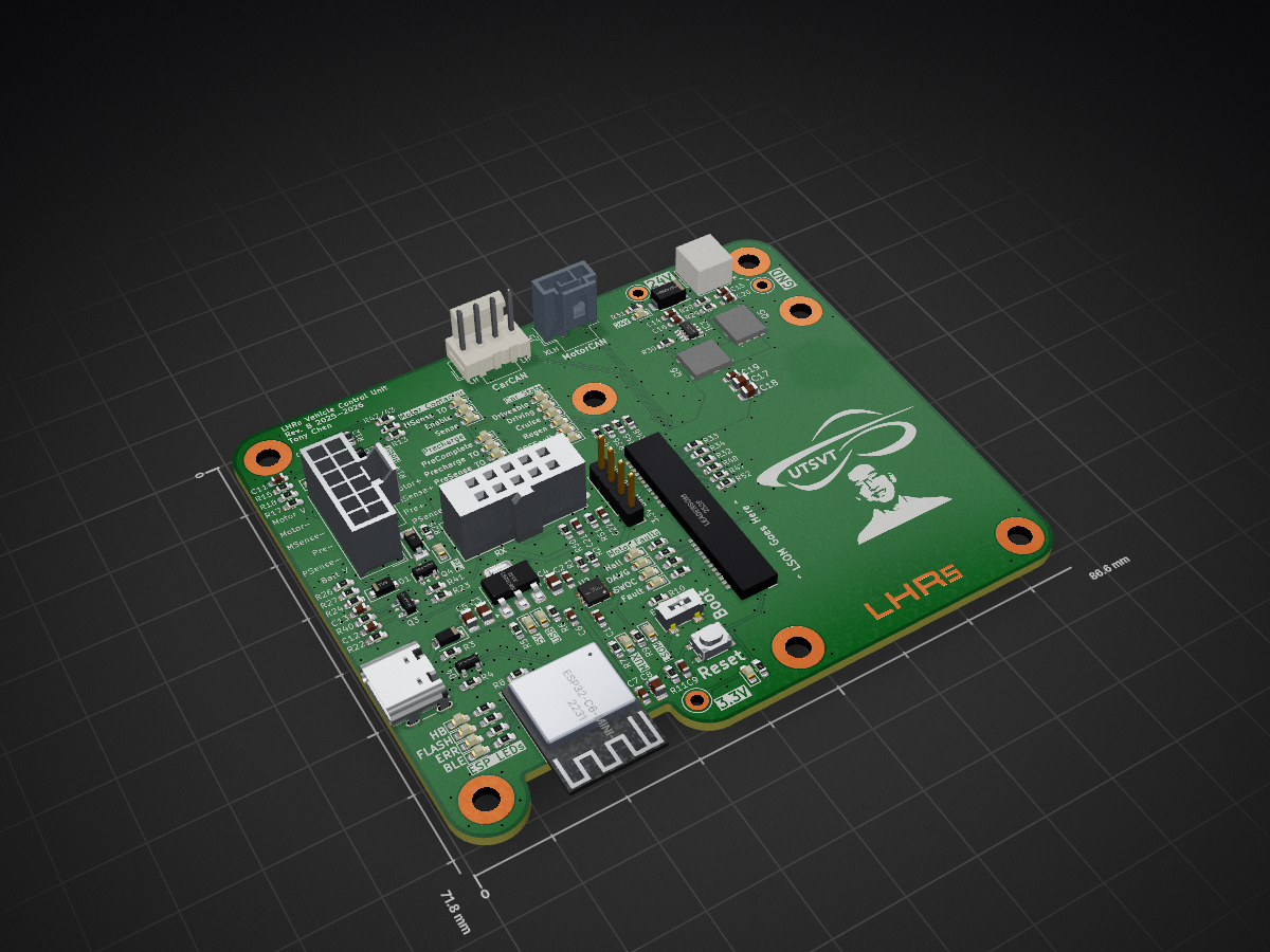
VehicleControlUnit is an open-source printed circuit board by lhr-solar, from the lhr-solar/VCAT-VehicleControlUnit repository on GitHub, published under the MIT licence. It is a 2-layer board of 86.6 × 71.8 mm with 142 parts on 150 nets, routed with 611 tracks and 400 vias.
It is built around the ESP32-C6-MINI-1U-H4, LT1963AEST-3.3#TRPBF and TPS2115ADRBR, with the IRLML0030, NVMFWS1D7N04XMT1G-VB and 1N5819HW-7-F-01 among its other parts. Its parts include 52 resistors, 22 capacitors, 11 diodes, 10 connectors and 6 transistors. It belongs with the ESP32 and RISC-V boards of this library.


Vehicle Control Unit (VCU) for the 2026 Longhorn Racing Solar car
Clone this repository using the following command
git clone git@github.com:lhr-solar/PS-VehicleControlUnit.git --recursiveFollow the installation instructions for your specific platform, found here.
Additionally, install the Arduino IDE
All firmware is stored in the Firmware/ directory and must be run while in a nix shell. For the first time you will need to run
chmod +x ./run_nix.sh
./run_nix.sh
This will place you in a nix shell with all needed dependencies. After the first time, you only need to run the below command to enter the nix shell.
./run_nix.shTo compile production firmware, simply run:
makeTo compile a specific test file, run:
make TEST=[name of test excluding .c and test_]Test files are located in test/ and must have the prefix test_ or else the test won't compile correctly. If you want to run the blinky test, which is located in tests/blinky_test.c you will run
make TEST=blinky| Qty | Value | Footprint | References |
|---|---|---|---|
| 24 | 1k | Resistor_SMD:R_0603_1608Metric_Pad0.98x0.95mm_HandSolder | R1, R15, R24, R32, R33, R34, R35, R36, R37, R38, R39, R40, R41, R42, R43, R44 +8 |
| 13 | 10k | Resistor_SMD:R_0603_1608Metric_Pad0.98x0.95mm_HandSolder | R2, R8, R10, R11, R12, R13, R17, R18, R22, R23, R26, R27, R28 |
| 11 | 0.1u | Capacitor_SMD:C_0603_1608Metric_Pad1.08x0.95mm_HandSolder | C1, C2, C6, C7, C9, C11, C13, C15, C19, C21, C22 |
| 7 | 120 | Resistor_SMD:R_0603_1608Metric_Pad0.98x0.95mm_HandSolder | R6, R7, R9, R16, R19, R20, R21 |
| 6 | 10u | Capacitor_SMD:C_0805_2012Metric_Pad1.18x1.45mm_HandSolder | C3, C4, C5, C8, C17, C18 |
| 4 | 1u | Capacitor_SMD:C_0603_1608Metric_Pad1.08x0.95mm_HandSolder | C10, C12, C14, C20 |
| 4 | IRLML0030 | Package_TO_SOT_SMD:SOT-23 | Q1, Q2, Q3, Q4 |
| 4 | PWR | LED_SMD:LED_0603_1608Metric_Pad1.05x0.95mm_HandSolder | D5, D6, D7, D8 |
| 3 | 4.3k | Resistor_SMD:R_0603_1608Metric_Pad0.98x0.95mm_HandSolder | R14, R25, R31 |
| 3 | LED | LED_SMD:LED_0603_1608Metric_Pad1.05x0.95mm_HandSolder | Con1, Con2, LVPWR1 |
| 3 | LOGO | LOGO | G***, G***, G*** |
| 3 | MountingHole | MountingHole:MountingHole_3.2mm_M3_Pad_TopBottom | H1, H2, H3 |
| 3 | TestPoint | TestPoint:TestPoint_Keystone_5005-5009_Compact | 3V1, 24V_TP1, LVGND_TP1 |
| 2 | 5.1k | Resistor_SMD:R_0603_1608Metric_Pad0.98x0.95mm_HandSolder | R3, R4 |
| 2 | D | UTSVT_Passives:SODFL4724X108N | D9, D10 |
| 2 | Driving | LED_SMD:LED_0603_1608Metric_Pad1.05x0.95mm_HandSolder | LV21, LV22 |
| 2 | HB | LED_SMD:LED_0603_1608Metric_Pad1.05x0.95mm_HandSolder | LV1, LV17 |
| 2 | NVMFWS1D7N04XMT1G | UTSVT_Power:NVMFWS3D0P04M8LT1G | Q5, Q6 |
| 2 | PT | LED_SMD:LED_0603_1608Metric_Pad1.05x0.95mm_HandSolder | LV6, LV23 |
| 2 | TVS | Diode_SMD:D_SOD-123F | D1, D2 |
| 1 | 1N5819HW-7-F | Diode_SMD:D_SOD-123 | D3 |
| 1 | 200k | Resistor_SMD:R_0603_1608Metric_Pad0.98x0.95mm_HandSolder | R29 |
| 1 | 220n | Capacitor_SMD:C_0603_1608Metric_Pad1.08x0.95mm_HandSolder | C16 |
| 1 | 3.3V Injector | Connector_PinHeader_2.54mm:PinHeader_1x04_P2.54mm_Vertical | J3 |
| 1 | 450 | Resistor_SMD:R_0603_1608Metric_Pad0.98x0.95mm_HandSolder | R5 |
| 1 | 9k | Resistor_SMD:R_0603_1608Metric_Pad0.98x0.95mm_HandSolder | R30 |
| 1 | BF | LED_SMD:LED_0603_1608Metric_Pad1.05x0.95mm_HandSolder | LV9 |
| 1 | BLE | LED_SMD:LED_0603_1608Metric_Pad1.05x0.95mm_HandSolder | LV4 |
| 1 | BOOT | UTSVT_Special:SW_CJS-1200TA | SW2 |
| 1 | CarCAN | UTSVT_Connectors:Molex_Nano-Fit_105309-xx04_1x04_P2.50mm_Vertical | J4 |
| 1 | CarLVPowerConnector | UTSVT_Connectors:Molex_Nano-Fit_105309-xx02_1x02_P2.50mm_Vertical | J7 |
| 1 | Cruise | LED_SMD:LED_0603_1608Metric_Pad1.05x0.95mm_HandSolder | LV19 |
| 1 | Dr. Hallock | UTSVT_Logos:LHRs_LOGO | LOGO2 |
| 1 | Dr. Hallock | UTSVT_Logos:Hallock_Image_Tiny | LOGO1 |
| 1 | ERR | LED_SMD:LED_0603_1608Metric_Pad1.05x0.95mm_HandSolder | LV3 |
| 1 | ESP32-C6-MINI-1/U | UTSVT_Special:ESP32-C6-MINI-1 | U4 |
| 1 | FLASH | LED_SMD:LED_0603_1608Metric_Pad1.05x0.95mm_HandSolder | LV2 |
| 1 | HALL | LED_SMD:LED_0603_1608Metric_Pad1.05x0.95mm_HandSolder | LV12 |
| 1 | LED1 | LED_SMD:LED_0603_1608Metric_Pad1.05x0.95mm_HandSolder | LV13 |
| 1 | LED2 | LED_SMD:LED_0603_1608Metric_Pad1.05x0.95mm_HandSolder | LV14 |
| 1 | LED3 | LED_SMD:LED_0603_1608Metric_Pad1.05x0.95mm_HandSolder | LV15 |
| 1 | LED4 | LED_SMD:LED_0603_1608Metric_Pad1.05x0.95mm_HandSolder | LV16 |
| 1 | LM74502HDDFR | UTSVT_Power:SOT65P280X110-8N | IC1 |
| 1 | LT1963AEST-3.3#TRPBF | Package_TO_SOT_SMD:SOT-223-3_TabPin2 | U3 |
| 1 | LeaderSOM | UTSVT_Special:LeaderSOM | U1 |
| 1 | MF | LED_SMD:LED_0603_1608Metric_Pad1.05x0.95mm_HandSolder | LV8 |
| 1 | MW | LED_SMD:LED_0603_1608Metric_Pad1.05x0.95mm_HandSolder | LV11 |
| 1 | MotorCAN | UTSVT_Connectors:Molex_Nano-Fit_105309-xx03_1x03_P2.50mm_Vertical | J5 |
| 1 | PC | LED_SMD:LED_0603_1608Metric_Pad1.05x0.95mm_HandSolder | LV5 |
| 1 | Precharge Connector | UTSVT_Connectors:Molex_Nano-Fit_105310-xx12_2x06_P2.50mm_Vertical | J1 |
| 1 | RESET | Boot Switch:TL3365AF180QG | SW1 |
| 1 | Regen | LED_SMD:LED_0603_1608Metric_Pad1.05x0.95mm_HandSolder | LV18 |
| 1 | SFH11-PBPC-D05-ST-BK | UTSVT_Connectors:CONN_SFH11-xxxC-D05-ST-XX_SUL | J2 |
| 1 | SMAF4758A | UTSVT_Passives:SODFL5026X125N | D11 |
| 1 | SP0503BAHT | Package_TO_SOT_SMD:SOT-143 | D4 |
| 1 | ST | LED_SMD:LED_0603_1608Metric_Pad1.05x0.95mm_HandSolder | LV7 |
| 1 | SWOC | LED_SMD:LED_0603_1608Metric_Pad1.05x0.95mm_HandSolder | LV10 |
| 1 | Safe | LED_SMD:LED_0603_1608Metric_Pad1.05x0.95mm_HandSolder | LV20 |
| 1 | TPS2115ADRBR | UTSVT_ICs:SON65P300X300X100-9N | U2 |
| 1 | USB_C_Receptacle_USB2.0_16P | UTSVT_Connectors:USB_C_Receptacle_GCT_USB4105-xx-A_16P_TopMnt_Horizontal | J6 |

lhr-solar/PS-ChargerInterfacePCB
Interfaces the Elcon charger with the BPS/Battery over CAN

lhr-solar/PS-PumpController
Controls speed of liquid cooling pump and fans for the main battery pack. Additionally, interprets data from temperature sensors and flowrate sensors for fan/pump control loop

lhr-solar/PS-MotorControllerInterfacePCB
Provides power conversion/protection and fan control for the Prohelion WaveSculptor 22 motor controller

gabriele-moretto/dinospand
Agricultural PCB project design and firmware developing.


It measures 86.6 × 71.8 mm and has 2 copper layers, 1.6 mm thick.
142 parts, built around the ESP32-C6-MINI-1U-H4, LT1963AEST-3.3#TRPBF, TPS2115ADRBR and IRLML0030. The full list of its parts is on this page, with links to each part's symbol and footprint where PCBKit's library has them.
From the lhr-solar/VCAT-VehicleControlUnit repository on GitHub, at the commit this page was made from: the board is Hardware/VehicleControlUnit.kicad_pcb and its schematic Hardware/ActivePrecharge.kicad_sch. PCBKit opens the board in the browser, with nothing to install.
Its repository publishes it under the MIT licence: you may reuse it on that licence's terms (keep the author's notice, and for a copyleft licence share your changes alike).