8 layers120 × 60 mm
Jetson orin baseboard
antmicro/jetson-orin-baseboard
Baseboard targetting the NVIDIA Jetson Orin Nano and Jetson Orin NX
681 parts305Apache-2.0

 lhr-solar/PS-PowerBoard
The secondary power board
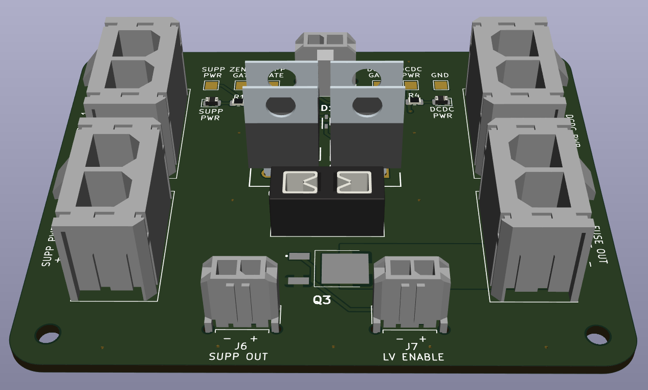
Power Secondary is an open-source printed circuit board by lhr-solar, from the lhr-solar/PS-PowerBoard repository on GitHub. It is a 4-layer board of 79.4 × 58.3 mm with 99 parts on 50 nets, routed with 277 tracks and 222 vias.
It is built around the 74LVC2G07GV,125-JSM and SQJQ140E-T1_GE3. Its parts include 31 resistors, 9 capacitors, 6 transistors, 4 ICs and 4 diodes.


Author: Pratyush Patra and Jason Kacines
This board takes inputs from the DCDC converter and the Supplemental Battery and selects which source to output to the fuse box. DCDC is the power from the high voltage primary battery pack that gets stepped down to 12V through the DCDC converter. The supplemental battery pack is the low voltage 12V NiMH battery pack. When DCDC is on, the board will select DCDC, and when DCDC is off, the board will select the Supplemental Battery. The supplemental should only be selected during ignition and the fault state. The board selects the source using a 10V zener diode that will breakdown once DCDC is above 10V.
This board also interfaces with both the Supplemental Monitoring PCB and Ignition Switch:
Interactive BOM (Must download and open in browser)
| # | Name | Type | Ideal Voltage | Notes |
|---|---|---|---|---|
| J1 | SUPP PWR MON | 1x02_P3.00mm_Vertical Female | +12V | 9.9 mm tall |
| J2 | SUPP PWR 1 | 1x02_P7.49mm_Vertical Female | +12V | 14.76 mm tall |
| J3 | SUPP PWR 2 | 1x02_P7.49mm_Vertical Female | +12V | 14.76 mm tall |
| J4 | DCDC PWR | 1x02_P7.49mm_Vertical Female | +12V | 14.76 mm tall |
| J5 | FUSE OUT | 1x02_P7.49mm_Vertical Female | +12V | 14.76 mm tall |
| J6 | SUPP OUT | 1x02_P3.00mm_Vertical Female | +12V | 9.9 mm tall |
| J7 | LV ENABLE | 1x02_P3.00mm_Vertical Female | +12V | 9.9 mm tall |
The tallest components are the Power MOSFETs(Q1A1, Q1A2, Q1A3, Q1A4) which are 18.5 mm tall and the connectors which are 14.76 mm tall.
| Qty | Value | Footprint | References |
|---|---|---|---|
| 17 | 100K | Resistor_SMD:R_0805_2012Metric | R11, R12, R13, R14, R15, R16, R17, R19, R20, R21, R22, R23, R24, R25, R26, R27 +1 |
| 13 | TestPoint | UTSVT_Special:TestPoint_HEX_3mmID | CH1, CH2, DCDC, FAULT1, FAULT2, GATE1, GATE2, GND, INTVCC, OUT, SUPP, VALID1, VALID2 |
| 7 | 10u | Capacitor_SMD:C_0805_2012Metric | C1, C2, C4, CMOSFET1, CMOSFET3, CTMR1, CTMR2 |
| 6 | 5.76M | Resistor_SMD:R_0805_2012Metric | R3, R5, R7, R9, R29, R31 |
| 6 | LED | LED_SMD:LED_0805_2012Metric | DCDC_CH, DCDC_FAULT, DCDC_VALID, SUPP_CH, SUPP_FAULT, SUPP_VALID |
| 6 | LOGO | LOGO | G***, G***, G***, G***, G***, G*** |
| 4 | MountingHole | MountingHole:MountingHole_3mm | H1, H2, H3, H4 |
| 4 | PowerConn | Connector_Molex:Molex_Sabre_43160-0102_1x02_P7.49mm_Vertical | CRITICAL, DCDC, NON-CRITICAL, SUPP |
| 4 | SQJQ140E-T1_GE3 | PowerBoardLib:TO200P800X182-5N | Q1, Q2, Q3, Q4 |
| 3 | 74LVC2G07GV,125 | Package_TO_SOT_SMD:ROHM_SOT-457_ClockwisePinNumbering | U3, U4, U5 |
| 2 | , | ||
| 2 | 0.1u | Capacitor_SMD:C_0805_2012Metric | C3, C5 |
| 2 | 1.2 | Resistor_SMD:R_0805_2012Metric | R1, R2 |
| 2 | 1m | PowerBoardLib:RESC6432X89N | RSENSE1, RSENSE2 |
| 2 | 1u | Capacitor_SMD:C_0805_2012Metric | CCPO1, CINTVCC1 |
| 2 | 215K | Resistor_SMD:R_0805_2012Metric | R8, R30 |
| 2 | 261K | Resistor_SMD:R_0805_2012Metric | R4, R10 |
| 2 | 287K | Resistor_SMD:R_0805_2012Metric | R6, R32 |
| 2 | D_Zener | Diode_SMD:D_SOD-523 | D9, D11 |
| 2 | SMBJ15D-M3I | PowerBoardLib:P26_DO-214AA_SMB | D1, D2 |
| 1 | 1.2m | PowerBoardLib:EEUFS1C122LB | COUT1 |
| 1 | 500p | Capacitor_SMD:C_0603_1608Metric | CQUAL1 |
| 1 | DIS1 Jumper | Connector_PinHeader_2.54mm:PinHeader_1x03_P2.54mm_Vertical | DISABLE1 |
| 1 | DIS2 Jumper | Connector_PinHeader_2.54mm:PinHeader_1x03_P2.54mm_Vertical | DISABLE2 |
| 1 | LTC4421CG-PBF | PowerBoardLib:G_05-08-1640_ADI | U2 |
| 1 | PMOS | Package_TO_SOT_SMD:SOT-23-3 | Q6 |
| 1 | PowerConn | UTSVT_Connectors:Molex_MicroFit3.0_1x2xP3.00mm_PolarizingPeg_Vertical | SUPP MON |
| 1 | RETRY Jumper | Connector_PinHeader_2.54mm:PinHeader_1x03_P2.54mm_Vertical | RETRY |
| 1 | SQJ141ELP | Package_SO:PowerPAK_SO-8L_Single | Q5 |
antmicro/jetson-orin-baseboard
Baseboard targetting the NVIDIA Jetson Orin Nano and Jetson Orin NX

antmicro/rdimm-ddr4-tester
Experimental platform built around Xilinx Kintex-7 FPGA for development and customization of RAM controllers supporting RDIMM DDR4 RAM modules used in data centers.


AtlasAutoware/carv2
Atlas Autoware car v2: drive board (ESC, BMS, USB-C charging), Jetson carrier, printed kit

polpo/picogus
Emulation of ISA sound cards and CD-ROM on Raspberry Pi Pico (GUS, SB/Adlib, MPU-401, Tandy, CMS, Panasonic CD-ROM) with USB mouse/joystick support


1Bitsy/1bitsy-hardware
Small breadboard friendly STM32 (eventually other mcu's too) eval boards with exposed JTAG and SWD for the use with Black Magic Probe and others!

felixheld/qspimux
QSPI flash multiplexer - connect a SPI NOR flash to either an embedded system or a programmer for remote firmware tests
It measures 79.4 × 58.3 mm and has 4 copper layers, 1.6 mm thick.
99 parts, built around the 74LVC2G07GV,125-JSM and SQJQ140E-T1_GE3. The full list of its parts is on this page, with links to each part's symbol and footprint where PCBKit's library has them.
From the lhr-solar/PS-PowerBoard repository on GitHub, at the commit this page was made from: the board is Power-Secondary.kicad_pcb and its schematic LTC4421.kicad_sch. PCBKit opens the board in the browser, with nothing to install.
Its repository states no licence, so its author keeps all rights: ask lhr-solar before reusing the design.