2 layers60 × 30 mm
Controller
google/mozc-devices
Circuit diagrams and firmware source code for Gboard DIY keyboards
11 parts3kApache-2.0
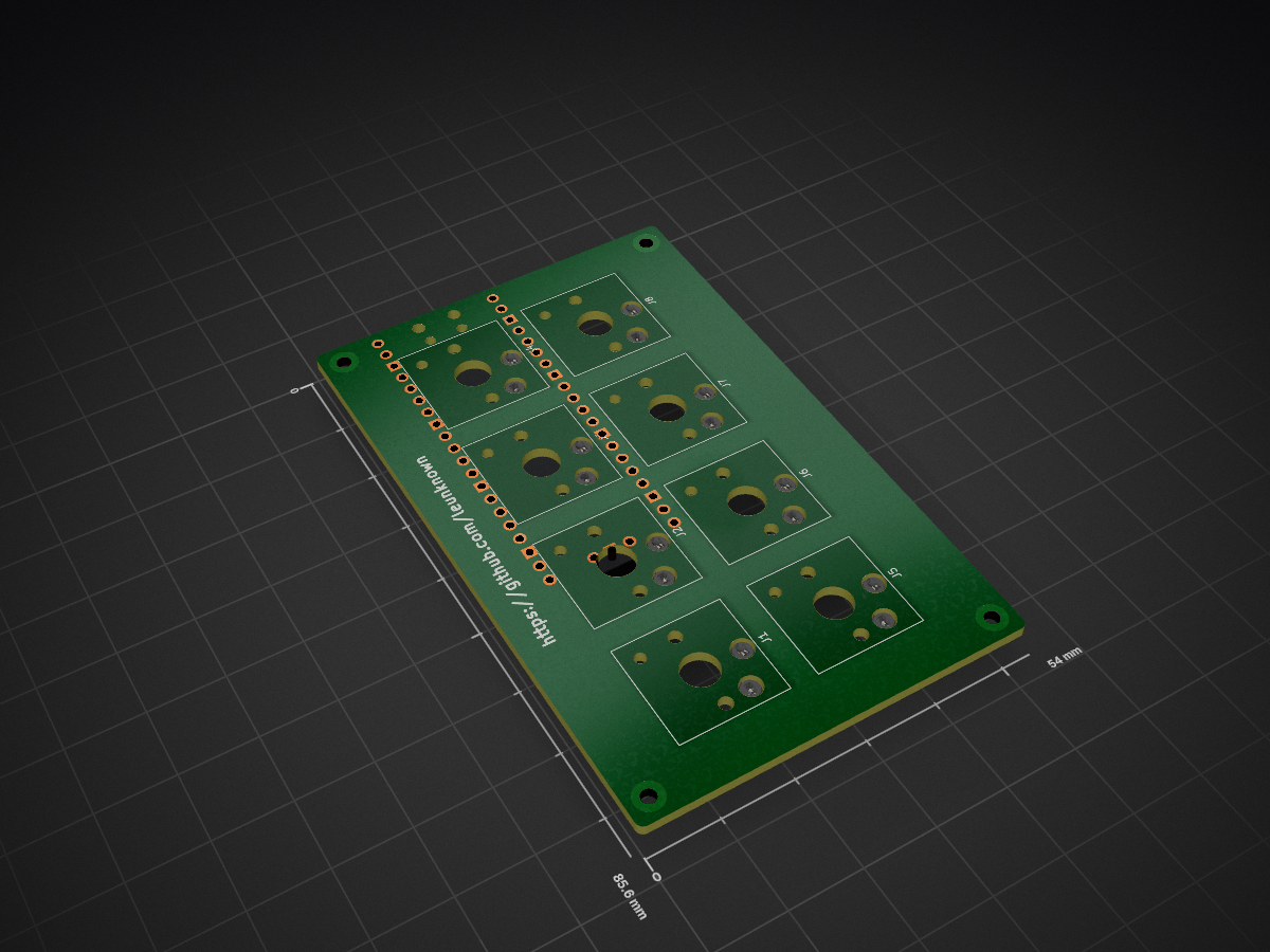
 leunknown/MacroCard-LP1
8 Key Macro Pad Kailh Choc
Macropad LP is an open-source printed circuit board by leunknown, from the leunknown/MacroCard-LP repository on GitHub, published under the MIT licence. It is a 2-layer board of 54 × 85.6 mm with 11 parts on 43 nets, routed with 33 tracks and 4 vias.
Its parts include 8 connectors and 1 IC. It belongs with the keyboards and input boards and the RP2040 boards of this library.
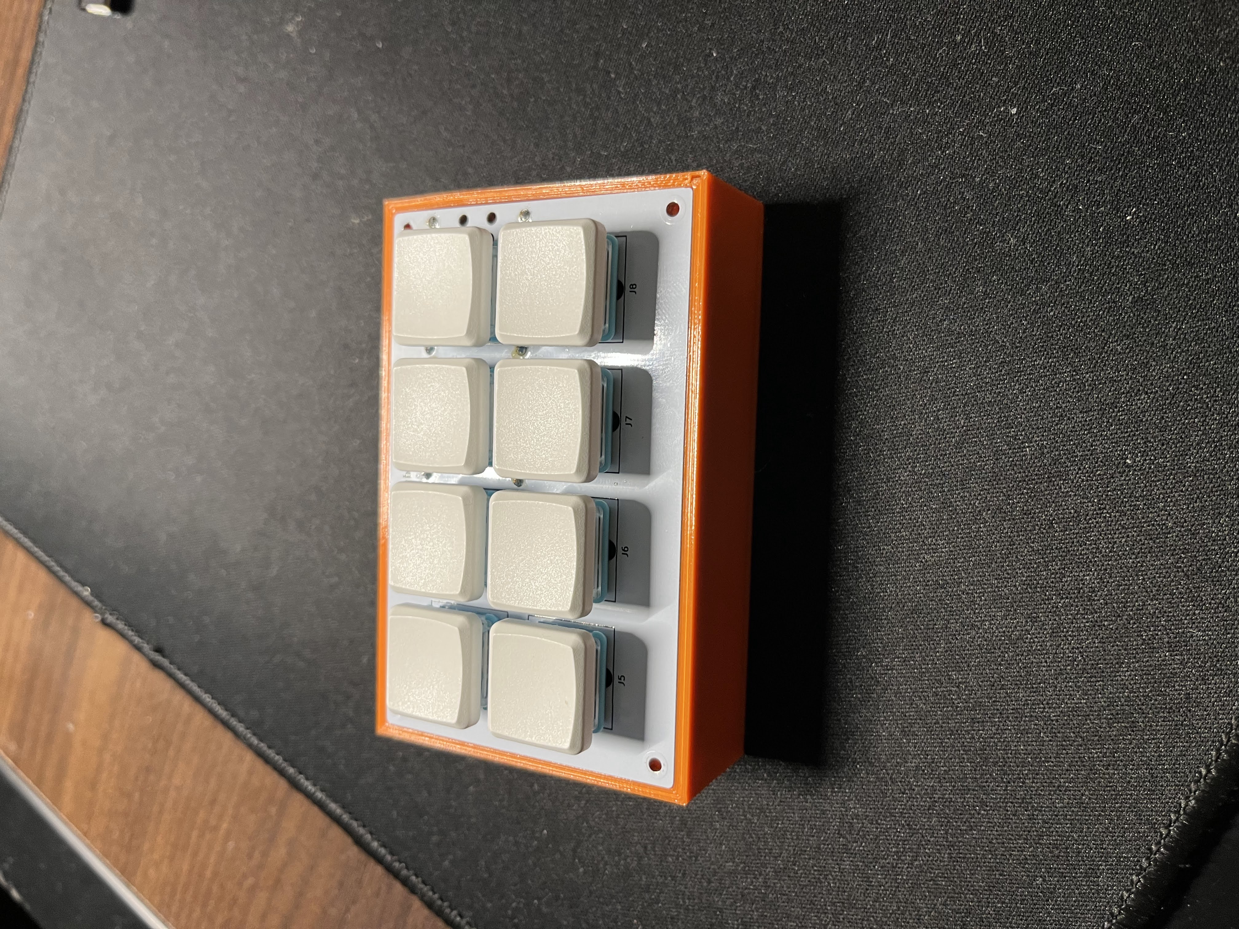
A simple credit card sized PCB made for an 8 Key Macropad powered by a Raspberry Pi Pico
First solder the Kailh hotswap sockets to the back. An easy way to do it is to put solder on one side of the PCB contact, then solder one side and then the other afterwards.
Put Male headers (long side) on breadboard and afterwards put the pico on the pins and solder. We do it this way to ensure the header pins are straight.
Put the Female header pins onto the pico pins, align it with the back of the PCB (where there is an image of a person and solder the Female headers in place.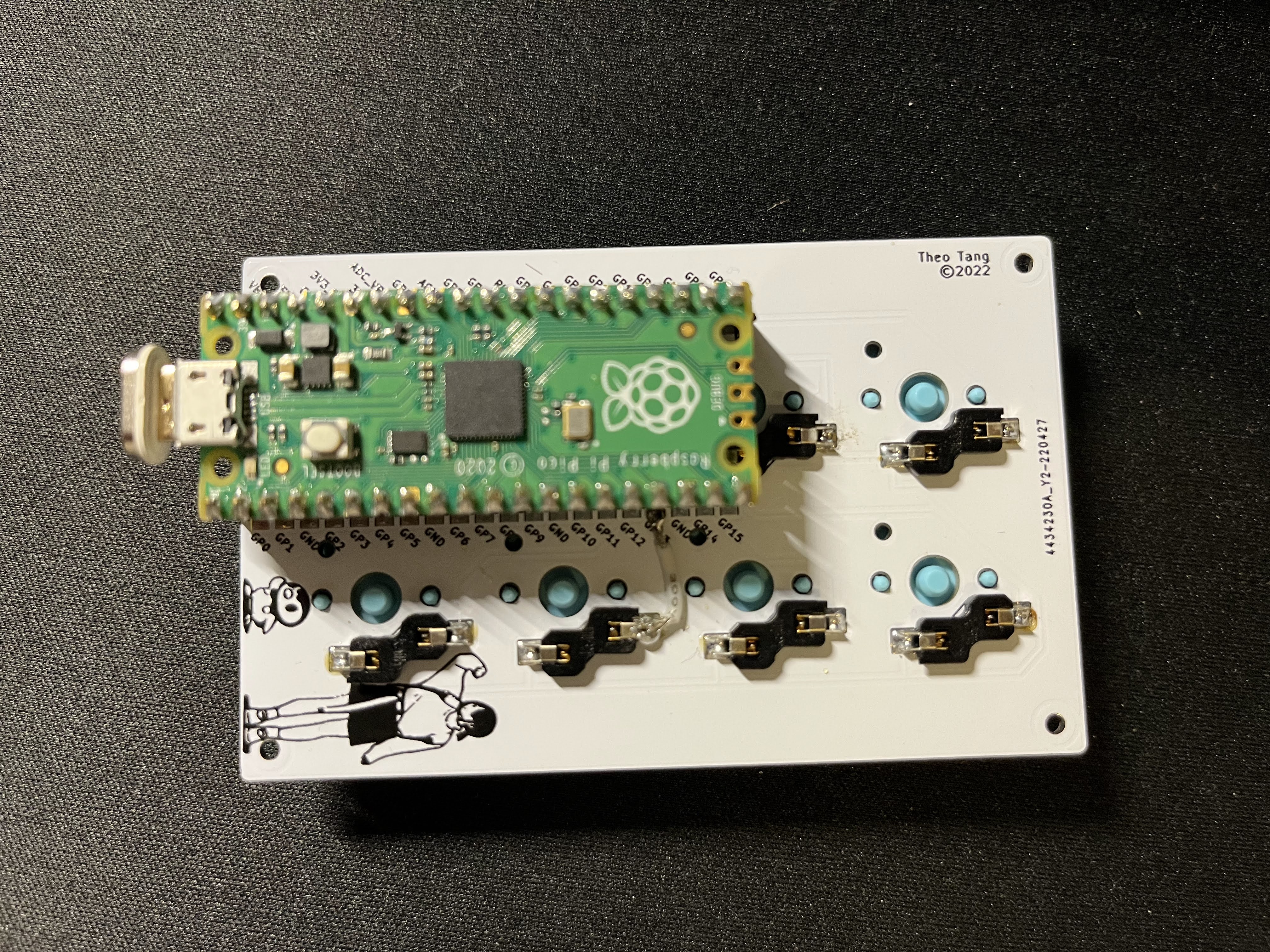
Solder the rest of the SMD hotswap sockets by first tinning one pad, then placing the socket and heat up the part touching the tinned pad. Afterwards, solder the other pad. Repeat this process until all sockets are soldered on.
To code the Pico, pick a programming language to use and code!
| Qty | Value | Footprint | References |
|---|---|---|---|
| 1 | LOGO | Library:piplup | G*** |
| 1 | LOGO | Library:piplup mirrored | G*** |
| 1 | Pico | MCU_RaspberryPi_and_Boards:RPi_Pico_SMD_TH | U1 |
| 1 | switch 1 | Switch_Keyboard_Hotswap_Kailh:SW_Hotswap_Kailh_Choc_V1V2 | J1 |
| 1 | switch 2 | Switch_Keyboard_Hotswap_Kailh:SW_Hotswap_Kailh_Choc_V1V2 | J2 |
| 1 | switch 3 | Switch_Keyboard_Hotswap_Kailh:SW_Hotswap_Kailh_Choc_V1V2 | J3 |
| 1 | switch 4 | Switch_Keyboard_Hotswap_Kailh:SW_Hotswap_Kailh_Choc_V1V2 | J4 |
| 1 | switch 5 | Switch_Keyboard_Hotswap_Kailh:SW_Hotswap_Kailh_Choc_V1V2 | J5 |
| 1 | switch 6 | Switch_Keyboard_Hotswap_Kailh:SW_Hotswap_Kailh_Choc_V1V2 | J6 |
| 1 | switch 7 | Switch_Keyboard_Hotswap_Kailh:SW_Hotswap_Kailh_Choc_V1V2 | J7 |
| 1 | switch 8 | Switch_Keyboard_Hotswap_Kailh:SW_Hotswap_Kailh_Choc_V1V2 | J8 |
google/mozc-devices
Circuit diagrams and firmware source code for Gboard DIY keyboards


FrameworkComputer/ExpansionCards
Reference designs and documentation to create Expansion Cards for the Framework Laptop

hoglet67/RGBtoHDMI
Bare-metal Raspberry Pi project that provides pixel-perfect sampling of Retro Computer RGB/YUV video and conversion to HDMI

hackclub/OnBoard
💡 Join 1,000 teenagers and make your first PCB with a $100 grant!


tardate/LittleArduinoProjects
a collection of "Little Electronic & Arduino Projects", most involving electronics or an Arduino in one way or another!

basilfx/TRADFRI-Hacking
Hacking IKEA TRÅDFRI products, such as light bulbs, window blinds and other accessories.
It measures 54 × 85.6 mm and has 2 copper layers, 1.6 mm thick.
11 parts. The full list of its parts is on this page, with links to each part's symbol and footprint where PCBKit's library has them.
From the leunknown/MacroCard-LP repository on GitHub, at the commit this page was made from: the board is Macropad LP/Macropad LP.kicad_pcb and its schematic Macropad LP/Macropad LP.kicad_sch. PCBKit opens the board in the browser, with nothing to install.
Its repository publishes it under the MIT licence: you may reuse it on that licence's terms (keep the author's notice, and for a copyleft licence share your changes alike).