2 layers18.5 × 11.1 mm
Switch
byrantech/laptop
anyon_e, a highly integrated, high end, open source laptop. Attempt the impossible.
6 parts4.3kMIT

 letelescope/eqmod-bluetooth-dongle
This project demonstrates how to set a wireless Bluetooth connection for an EQMOD-compatible telescope mount using an HC-05 Bluetooth module.
Eqmod bluetooth dongle is an open-source printed circuit board by letelescope, from the letelescope/eqmod-bluetooth-dongle repository on GitHub, published under the MIT licence. It is a 2-layer board of 47 × 23.8 mm with 6 parts on 14 nets, routed with 21 tracks and 0 vias.
It belongs with the radio and wireless boards of this library.
Schematic diagrams and PCB layouts for the EQMOD Bluetooth dongle can be found in the electronics/eqmod-bluetooth-dongle/ directory.
electronics/eqmod-bluetooth-dongle/
├── footprints/                             # Electronic footprint files
├── eqmod-bluetooth-dongle.kicad_pro        # PCB project file
├── eqmod-bluetooth-dongle.kicad_sch        # Schematic file
├── eqmod-bluetooth-dongle.kicad_pcb        # PCB layout file
├── eqmod-bluetooth-dongle.kicad_prl        # PCB rules file
└──README.md # This fileAll this is very much inspired of the official EQDirect-BT schematic available on the EQMod website.
The EQMOD Bluetooth dongle is designed around the HC-05 Bluetooth module, which provides wireless serial communication capabilities. The schematic includes the necessary connections for power, ground, and serial communication (TX/RX) between the HC-05 module and the mount. The design also incorporates level shifting components to ensure compatibility between the HC-05 module's voltage levels and the mount's logic levels.
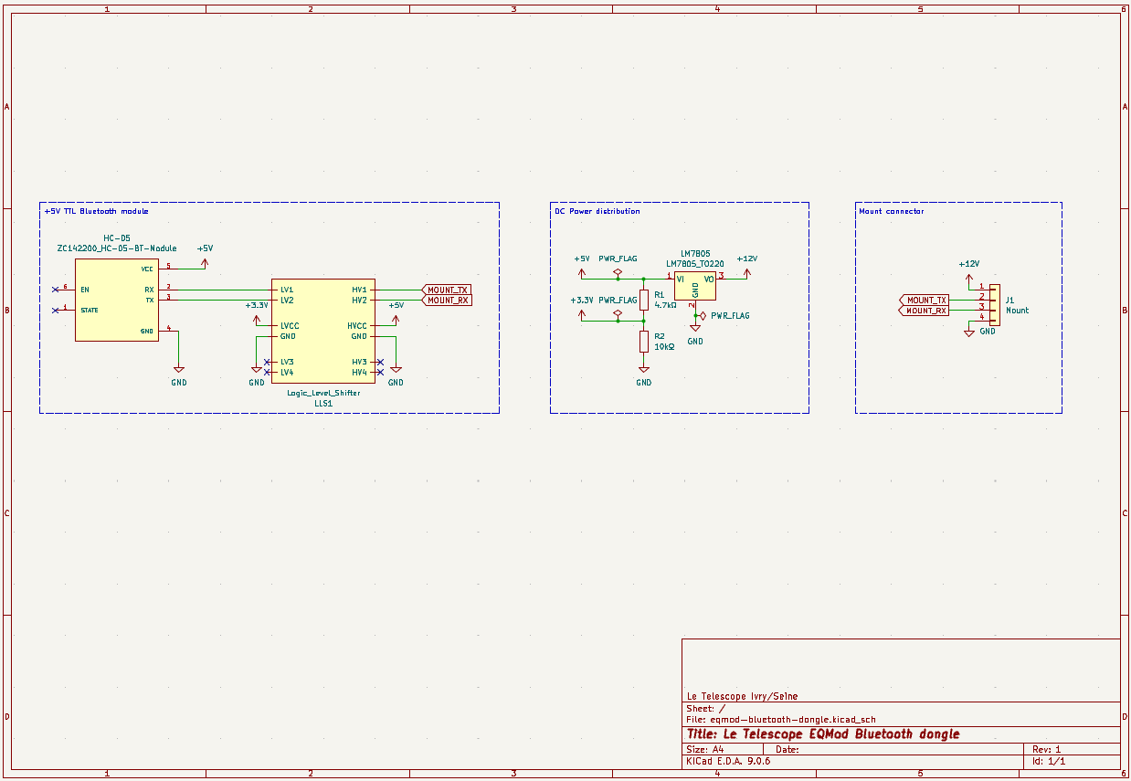
It consist of three sections:
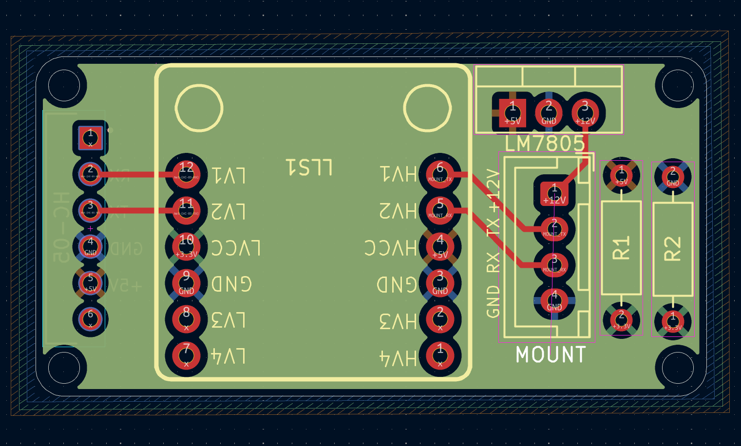
The PCB design implements the schematic, adhering to a straightforward routing strategy. This is a 4-layer PCB:
| Qty | Value | Footprint | References |
|---|---|---|---|
| 1 | 10kΩ | Resistor_THT:R_Axial_DIN0207_L6.3mm_D2.5mm_P10.16mm_Horizontal | R2 |
| 1 | 4.7kΩ | Resistor_THT:R_Axial_DIN0207_L6.3mm_D2.5mm_P10.16mm_Horizontal | R1 |
| 1 | LM7805_TO220 | Package_TO_SOT_THT:TO-220-3_Vertical | LM7805 |
| 1 | Logic_Level_Shifter | Soldered_Logic_Level_Shifter:333029_Logic_Level_Shifter | LLS1 |
| 1 | Mount | Connector_JST:JST_XH_B4B-XH-A_1x04_P2.50mm_Vertical | MOUNT |
| 1 | ZC142200_HC-05-BT-Module | ZC142200:MODULE_ZC142200_HC05 | HC-05 |
byrantech/laptop
anyon_e, a highly integrated, high end, open source laptop. Attempt the impossible.


Jcparkyn/dpoint
Open-source digital stylus using camera tracking and inertial measurements

VoronDesign/Voron-Hardware
Cool Hardware designed by the Voron Design group

hoglet67/RGBtoHDMI
Bare-metal Raspberry Pi project that provides pixel-perfect sampling of Retro Computer RGB/YUV video and conversion to HDMI

hackclub/OnBoard
💡 Join 1,000 teenagers and make your first PCB with a $100 grant!

Luos-io/luos_engine
Open-source and real-time orchestrator for cyber-physical-systems, to easily design, test and deploy embedded applications and digital twins.

It measures 47 × 23.8 mm and has 2 copper layers, 1.6 mm thick.
6 parts. The full list of its parts is on this page, with links to each part's symbol and footprint where PCBKit's library has them.
From the letelescope/eqmod-bluetooth-dongle repository on GitHub, at the commit this page was made from: the board is electronics/eqmod-bluetooth-dongle/eqmod-bluetooth-dongle.kicad_pcb and its schematic electronics/eqmod-bluetooth-dongle/eqmod-bluetooth-dongle.kicad_sch. PCBKit opens the board in the browser, with nothing to install.
Its repository publishes it under the MIT licence: you may reuse it on that licence's terms (keep the author's notice, and for a copyleft licence share your changes alike).