Skip to the content
PCBKitNew board
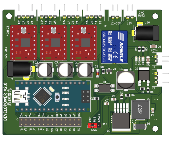
2 layers92 × 72.2 mmDevelopower v2.0, the printed circuit board in 3D

Developower-v2.0 Board

Size
92 × 72.2 mm
Copper layers
2
Thickness
1.6 mm
Parts
50
Nets
61
Pads
221
Tracks, vias
473, 36
Pours
6
Routed
Yes
KiCad
KiCad 7 (file 20221018)
Created
23 Dec 2019
Updated
1 Apr 2023

Overview

Developower v2.0 is an open-source printed circuit board by leoheck, from the leoheck/developower-v2.0 repository on GitHub. It is a 2-layer board of 92 × 72.2 mm with 50 parts on 61 nets, routed with 473 tracks and 36 vias.

It is built around the XL4015E1, SRD-12VDC-SL-C and SS54. Its parts include 16 connectors, 9 capacitors, 9 resistors, 5 diodes and 2 ICs. It belongs with the AVR (ATmega, ATtiny) boards of this library.

Main components

3

README

README.md

Developower-v2.0

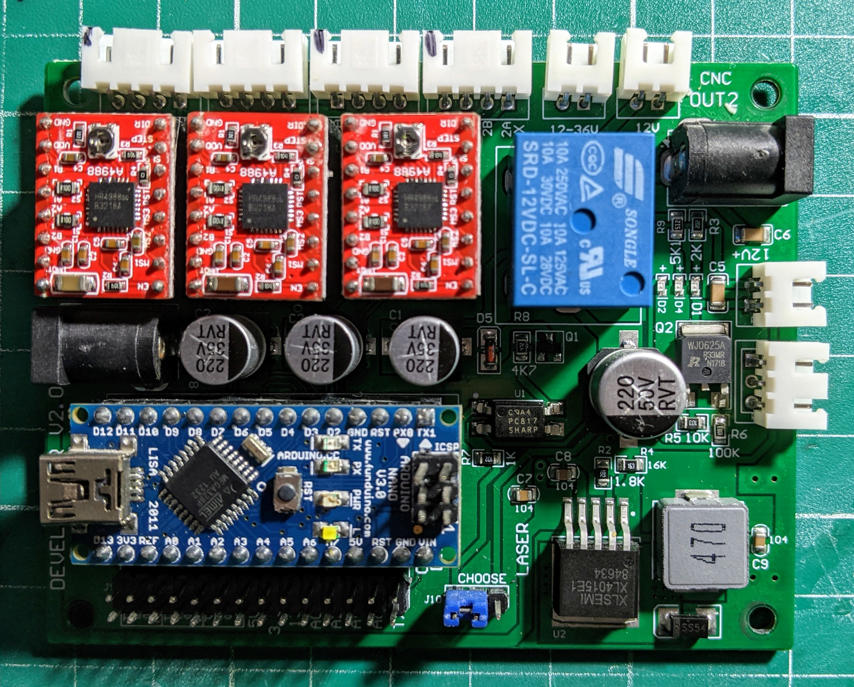
This project is an effort to recreate Developower-v2.0 board on Kicad.

This is the Developower-v2.0 board used on those Chinese 3018 CNC's.

This is the current version of the layout, but it is still a work in progress.

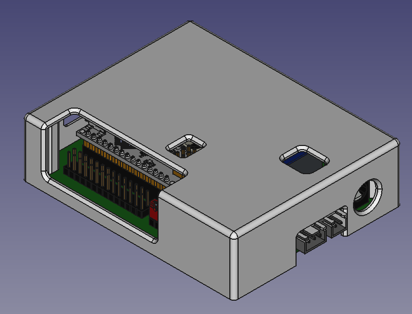
A simple cover for the board can be found here too.

Parts

50
QtyValueFootprintReferences
4MountingHoleMountingHole:MountingHole_3.2mm_M3H1, H2, H3, H4
3100nCapacitor_SMD:C_0805_2012MetricC7, C8, C9
3220/35VCapacitor_SMD:CP_Elec_8x10C1, C2, C3
3LEDLED_SMD:LED_0603_1608MetricD1, D2, D4
3Pololu_Breakout_A4988Developower:Pololu_Breakout-16_15.2x20.3mmJ2, J4, J6
2100nCapacitor_SMD:C_1206_3216MetricC5, C6
2YDevelopower:JST_S4B-XH-A(LF)(SN)J11, J13
1100kResistor_SMD:R_0805_2012MetricR6
110KResistor_SMD:R_0805_2012MetricR1
110kResistor_SMD:R_0805_2012MetricR5
112-36VDevelopower:BarrelJack_HorizontalJ7
112VDevelopower:JST_S2B-XH-A(LF)(SN)J12
112V-36VDevelopower:JST_S2B-XH-A(LF)(SN)J15
116kResistor_SMD:R_0805_2012MetricR4
11kResistor_SMD:R_0805_2012MetricR7
11k8Resistor_SMD:R_0805_2012MetricR2
1220/50VCapacitor_SMD:CP_Elec_10x10.5C4
12kResistor_SMD:R_0805_2012MetricR3
147u/5ADevelopower:L_Vishay_IHLP-4040L1
14k7Resistor_SMD:R_0805_2012MetricR8
15kResistor_SMD:R_0805_2012MetricR9
1Arduino_NanoDevelopower:Arduino_NanoJ8
1CNC_OUT2Developower:BarrelJack_HorizontalJ16
1LASERDevelopower:JST_S2B-XH-A(LF)(SN)J1
1Logo_Open_Hardware_SmallDevelopower:chinese-textT1
1MELFDiode_SMD:D_MiniMELFD5
1MiscConnector_PinHeader_2.54mm:PinHeader_2x14_P2.54mm_VerticalJ9
1ModeConnector_PinHeader_2.54mm:PinHeader_1x03_P2.54mm_VerticalJ10
1PC817Package_DIP:SMDIP-4_W9.53mmU1
1SRD-12VDC-SL-CDevelopower:Relay_SPDT_SANYOU_SRD_Series_Form_CK1
1SS54Diode_SMD:D_2512_6332MetricD3
1V_LASERDevelopower:JST_S3B-XH-A(LF)(SN)J3
1WJ0625APackage_TO_SOT_SMD:TO-252-2Q2
1XDevelopower:JST_S4B-XH-A(LF)(SN)J14
1XL4015E1Package_TO_SOT_SMD:TO-263-5_TabPin6U2
1Y2Package_TO_SOT_SMD:SC-59Q1
1ZDevelopower:JST_S4B-XH-A(LF)(SN)J5

Questions

How big is the Developower v2.0 PCB?

It measures 92 × 72.2 mm and has 2 copper layers, 1.6 mm thick.

What parts does the Developower v2.0 use?

50 parts, built around the XL4015E1, SRD-12VDC-SL-C and SS54. The full list of its parts is on this page, with links to each part's symbol and footprint where PCBKit's library has them.

Where can I download the Developower v2.0 KiCad files?

From the leoheck/developower-v2.0 repository on GitHub, at the commit this page was made from: the board is board.kicad_pcb and its schematic board.kicad_sch. PCBKit opens the board in the browser, with nothing to install.

Can I use the Developower v2.0 design in my own project?

Its repository states no licence, so its author keeps all rights: ask leoheck before reusing the design.

Similar boards

  • 4 layers144.2 × 82.8 mmSmartFuseBox, the printed circuit board in 3D

    SmartFuseBox

    k3ldar/PowerControlHub

    PowerControlHub is a flexible automation controller for 12V systems. It combines relay switching, sensor monitoring, and smart‑home connectivity (MQTT, Home Assistant, REST, BLE) into one device.

    93 parts5GPL-3.0
  • 2 layers80.9 × 92.7 mmEvo Borne, the printed circuit board in 3D

    Evo Borne

    SRA-VJTI/Evo-Borne

    This repository focuses on building an open-source morphobot.

    126 parts12MIT
  • 2 layers77.1 × 29.7 mmBuck converter, the printed circuit board in 3D

    Buck converter

    hasanberkdasar/Buck-converter

    XL4015 buck converter prototype: 8–30 V DC input to regulated 5 V USB-A output

    11 parts1MIT
  • 2 layers171.1 × 185.1 mmMpuled, the printed circuit board in 3D

    Mpuled

    abbounassima2/STM32-PLC-Runtime-Engine-and-PCB

    An STM32F407-based PLC runtime engine developed in Embedded C, together with a custom PLC controller PCB and a Renode-based simulation environment.

    189 parts
  • 4 layers110 × 36.6 mmXL4015-DC DC Buck Converter Schematic, the printed circuit board in 3D

    XL4015-DC DC Buck Converter Schematic

    ajvizganapathy-pixel/XL4015-BuckConverter-5A-PCB

    XL4015 5A step-down buck converter — KiCad PCB, gerbers, datasheets

    29 parts
  • 2 layers64.9 × 47.3 mmUniversal battery charger, the printed circuit board in 3D

    Universal battery charger

    ArthorH/PD-UniCharger

    Universal power delivery charger with battery reverse polarity protection

    64 partsCERN-OHL-P-2.0
  • 4 layers150 × 90 mmMultibay, the printed circuit board in 3D

    Multibay

    EdgeOfAssembly/multi-hdd-usb3-adapter

    USB3 multi-HDD adapter (PATA+SATA) — JLCPCB Gerbers/BOM

    131 parts
  • 2 layers91.4 × 75.6 mmBuck converter V6, the printed circuit board in 3D

    Buck converter V6

    HakanD1/24v-to-5v-50w-buck-converter-stm32

    24V to 5V 50W Digital Controlled Buck Converter Hardware, Software, and Control Design. Features an STM32-based closed-loop PI regulation, 120kHz PWM, custom PCB, and a Nextion HMI display interface.

    88 partsMIT