2 layers98 × 27 mm

 lekangji/Desk-Lock3
A cheap desk lock that unlocks with an NFC card.
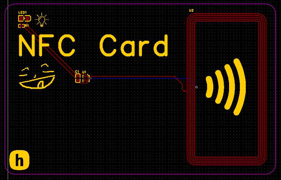
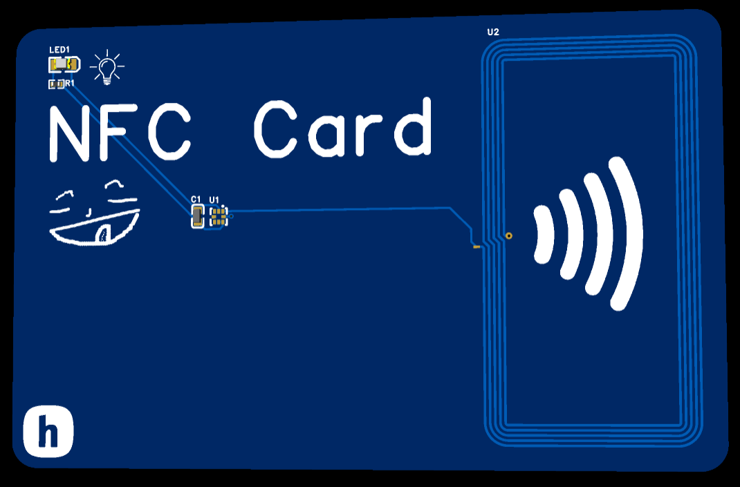
NFC Card3 is an open-source printed circuit board by lekangji, from the lekangji/Desk-Lock repository on GitHub. It is a 2-layer board of 85.6 × 54 mm with 5 parts on 5 nets, routed with 23 tracks and 1 via.
Its parts include 2 ICs, 1 capacitor, 1 resistor and 1 diode. It belongs with the radio and wireless boards of this library.
A cheap desk lock that unlocks with an NFC card.
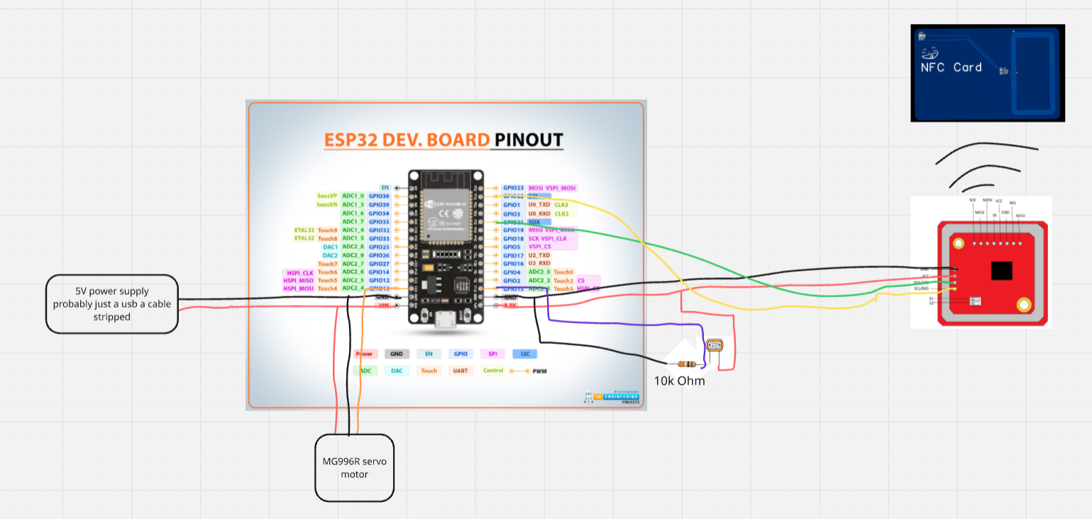
This project is a DIY desk lock which keeps items in your desk secure by using a NFC reader. An ESP32 reads an NFC card via a PN532 module and controls a servo motor that locks or unlocks the desk. A photoresistor is used to detect when the drawer is closed so it can relock automatically.
I wanted a secure way to lock my desk because I keep important items inside and my little brother cannot be trusted with it. Buying a commercial lock felt boring and expensive, so building one with NFC was more interesting and let me design my own NFC card and reader.
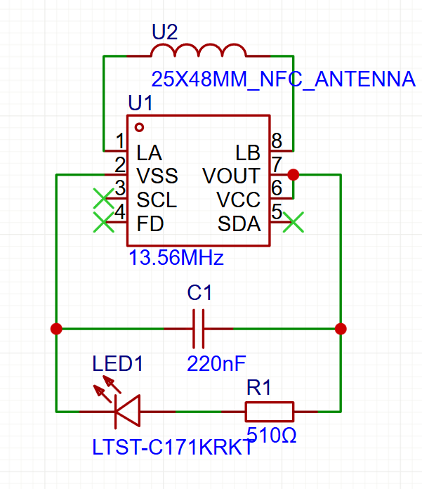
| Schematic | PCB | 3D View |
|---|---|---|
 |  |  |
This project is a DIY NFC-based desk lock using an ESP32. A PN532 NFC reader communicates with the ESP32 over I2C to read NFC cards. When an authorized card is detected, the ESP32 drives a servo motor to unlock the drawer. Unauthorized cards are ignored.
The servo is powered by an external supply that also powers the ESP32 and is mounted so one position locks the drawer and another unlocks it. The mechanical design is flexible and can support different desk types.
A photoresistor inside the drawer is wired as a voltage divider with a 10 kΩ resistor and connected to an ESP32 ADC pin. It detects whether the drawer is open or closed based on light level. After unlocking, the system waits until the drawer is closed (becomes dark), then automatically relocks after a configurable delay (default 10 seconds).
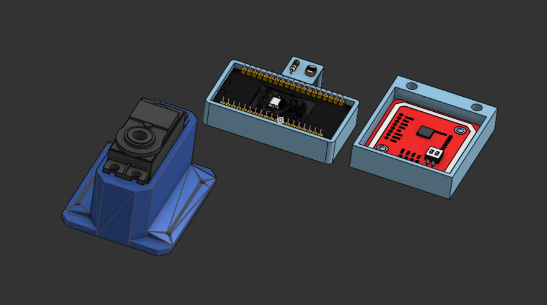
There is a case for every single part in this project:
Here is an example placement diagram for the servo:
The servo holder was not made by me, but suits the purpose perfectly.
| Qty | Value | Footprint | References |
|---|---|---|---|
| 1 | NFC Card3:R0402 | R1 | |
| 1 | NFC Card3:LED-SMD_L2.0-W1.25-RD_RED | LED1 | |
| 1 | NFC Card3:25X48MM_NFC_ANTENNA | U2 | |
| 1 | NFC Card3:XQFN-8_L1.6-W1.6-P0.50-BL_NT3H2111W0FHKH | U1 | |
| 1 | NFC Card3:C0603 | C1 |

joypad-ai/joypad-os
Universal controller firmware for building adapters, dongles, and custom controllers.

OLIMEX/OLINUXINO
OLINUXINO is Open Source / Open Hardware, low cost from EUR 24 Linux Industrial grade Single Board Computer capable to operate -25+85C

jamro/tiny-engineer
A small desktop robot that brings an AI coding assistant to life, physically acting out when it reads files, thinks, writes code, and finishes work.

hackclub/OnBoard
💡 Join 1,000 teenagers and make your first PCB with a $100 grant!


Luos-io/luos_engine
Open-source and real-time orchestrator for cyber-physical-systems, to easily design, test and deploy embedded applications and digital twins.
It measures 85.6 × 54 mm and has 2 copper layers, 1.6 mm thick.
5 parts. The full list of its parts is on this page, with links to each part's symbol and footprint where PCBKit's library has them.
From the lekangji/Desk-Lock repository on GitHub, at the commit this page was made from: the board is NFC Card/kicad/NFC Card3.kicad_pcb and its schematic NFC Card/kicad/NFC Card3.kicad_sch. PCBKit opens the board in the browser, with nothing to install.
Its repository states no licence, so its author keeps all rights: ask lekangji before reusing the design.