4 layers65 × 20 mm

 lekangji/Noctra-Devboard
A RP2350 based devboard with esp c6 mini integration for wifi + bluetooth.
DevboardV2 is an open-source printed circuit board by lekangji, from the lekangji/Noctra-Devboard repository on GitHub. It is a 4-layer board of 21 × 51 mm with 73 parts on 95 nets, routed with 571 tracks and 118 vias.
It is built around the ESP32-C6-MINI-1U-H4, W25Q128JVPIQ and HX4054A., with the TPD2EUSB30ADRTR and DMG1012T among its other parts. Its parts include 24 capacitors, 24 resistors, 7 ICs, 3 diodes and 3 connectors. It belongs with the radio and wireless and microcontroller boards boards and the ESP32, RP2350 and RISC-V boards of this library.


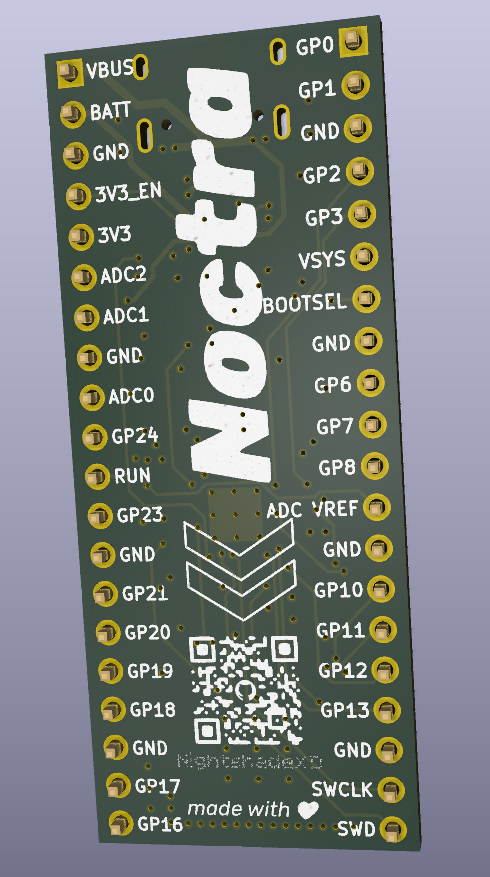
| Front Render | PCB |
|---|---|
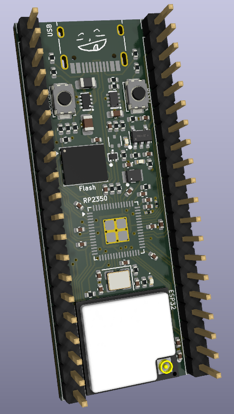 | 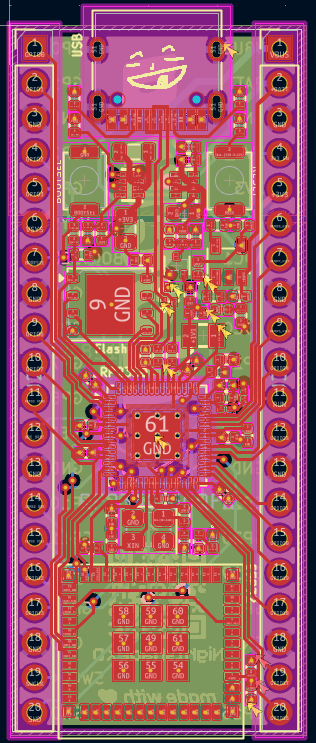 |
Like a normal Pico:
| Qty | Value | Footprint | References |
|---|---|---|---|
| 11 | 0.1uF | Capacitor_SMD:C_0402_1005Metric | C4, C5, C6, C7, C8, C9, C10, C11, C12, C19, C21 |
| 6 | 1K | Resistor_SMD:R_0402_1005Metric | R5, R6, R8, R9, R14, R22 |
| 5 | 4.7uF | Capacitor_SMD:C_0402_1005Metric | C3, C13, C14, C15, C16 |
| 5 | LOGO | LOGO | G***, G***, G***, G***, G*** |
| 4 | 100K | Resistor_SMD:R_0402_1005Metric | R10, R11, R20, R21 |
| 3 | LED | LED_SMD:LED_0402_1005Metric | D1, D2, D3 |
| 2 | 10K | Resistor_SMD:R_0402_1005Metric | R7, R19 |
| 2 | 10uF | Capacitor_SMD:C_0402_1005Metric | C22, C23 |
| 2 | 27 | Resistor_SMD:R_0402_1005Metric | R3, R4 |
| 2 | 33pF | Capacitor_SMD:C_0402_1005Metric | C17, C18 |
| 2 | 5.1K | Resistor_SMD:R_0402_1005Metric | R1, R2 |
| 2 | Conn_01x20 | Connector_PinHeader_2.54mm:PinHeader_1x20_P2.54mm_Vertical | J2, J3 |
| 2 | SW_Push | Button_Switch_SMD:SW_Push_SPST_NO_Alps_SKRK | SW1, SW2 |
| 1 | 1 | Resistor_SMD:R_0201_0603Metric | R23 |
| 1 | 12 MHz | Crystal:Crystal_SMD_3225-4Pin_3.2x2.5mm | Y1 |
| 1 | 1M | Resistor_SMD:R_0402_1005Metric | R17 |
| 1 | 1nF | Capacitor_SMD:C_0402_1005Metric | C20 |
| 1 | 1uF | Capacitor_SMD:C_0402_1005Metric | C24 |
| 1 | 2.2K | Resistor_SMD:R_0402_1005Metric | R18 |
| 1 | 200 | Resistor_SMD:R_0201_0603Metric | R24 |
| 1 | 22uF | Capacitor_SMD:C_0603_1608Metric | C1 |
| 1 | 2M | Resistor_SMD:R_0402_1005Metric | R16 |
| 1 | 33 | Resistor_SMD:R_0402_1005Metric | R15 |
| 1 | 47uF | Capacitor_SMD:C_0805_2012Metric | C2 |
| 1 | 511K | Resistor_SMD:R_0402_1005Metric | R13 |
| 1 | 91K | Resistor_SMD:R_0402_1005Metric | R12 |
| 1 | AOTA-B201610S3R3-3.3uH | EasyEDA:IND-SMD_L2.0-W1.6_AOTA-B201610S3R3-101-T | L2 |
| 1 | DMG1012T | Package_TO_SOT_SMD:SOT-523 | Q1 |
| 1 | ESP32-C6-MINI-1U-H4 | EasyEDA:WIFIM-SMD_61P-L13.2-W12.5-P0.80 | U6 |
| 1 | HX4054A. | EasyEDA:TSOT-23-5_L2.9-W1.6-P0.95-LS2.8-BL | U7 |
| 1 | LMSH2012081R0MTA-1uH | Inductor_SMD:L_0805_2012Metric | L1 |
| 1 | LOGO | Graphics:Logo_small | G*** |
| 1 | RP2350_60QFN | Package_DFN_QFN:QFN-60-1EP_7x7mm_P0.4mm_EP3.4x3.4mm_ThermalVias | U1 |
| 1 | TPD2EUSB30ADRTR | EasyEDA:SOT-723_L1.2-W0.8-P0.80-LS1.2-BR | U4 |
| 1 | TPS2116DRLR | EasyEDA:SOT-583-8_L2.1-W1.6-P0.50-LS1.6-BL | U5 |
| 1 | TPS631000DRLR | EasyEDA:SOT-583-8_L2.1-W1.2-P0.50-LS1.6-BL | U2 |
| 1 | USB_C_Receptacle_USB2.0_14P | Connector_USB:USB_C_Receptacle_HRO_TYPE-C-31-M-12 | J1 |
| 1 | W25Q128JVP | Package_SON:WSON-8-1EP_6x5mm_P1.27mm_EP3.4x4.3mm | U3 |
It measures 21 × 51 mm and has 4 copper layers, 1.6 mm thick.
73 parts, built around the ESP32-C6-MINI-1U-H4, W25Q128JVPIQ, HX4054A. and TPD2EUSB30ADRTR. The full list of its parts is on this page, with links to each part's symbol and footprint where PCBKit's library has them.
From the lekangji/Noctra-Devboard repository on GitHub, at the commit this page was made from: the board is pcb/kicad/DevboardV2.kicad_pcb and its schematic pcb/kicad/DevboardV2.kicad_sch. PCBKit opens the board in the browser, with nothing to install.
Its repository states no licence, so its author keeps all rights: ask lekangji before reusing the design.


anticitizn/p4eregrine
All-in-one ESP32 P4-based drone ESC, flight controller, and video processor

NicholasKorth/BedCooler
A dual-zone heating and cooling controller for a bed: a 6-layer KiCad board with an STM32G474 real-time controller and a Raspberry Pi Compute Module 5 host.

misko/prompt2device
The separate vNext PCB skill and orchestrator package is available alongside the reference workflow below; existing projects keep their accepted toolchain until an explicit migration.

emnyeca/emiuet
The thirteen positions preserve familiar guitar-derived voicings without forcing octave shifts or omissions. Expressive controls are deliberately constrained so that performance remains predictable: Pitch Bend is…

11philip22/tang-usb-ls-sniffer
A KiCad USB sniffer HAT for the Tang Nano 9K, designed to decode characters from compatible 1.5 Mb/s low-speed USB keyboards on the FPGA and send them over UART.