
2 layers100 × 80 mm

 LeftyDeMilo/clock-pulse-generator
ATtiny24 clock pulse generator with a two digit seven segment display for a breadboard projects
Clock pulse generator kicad scheme is an open-source printed circuit board by LeftyDeMilo, from the LeftyDeMilo/clock-pulse-generator repository on GitHub. It is a 2-layer board of 35.8 × 15.7 mm with 17 parts on 23 nets, routed with 129 tracks and 8 vias.
It is built around the ATTINY24A-MF. Its parts include 8 resistors, 4 connectors, 2 ICs, 1 capacitor and 1 diode. It belongs with the lEDs and displays boards and the AVR (ATmega, ATtiny) boards of this library.
Breadboard Clock Pulse Generator with manual and automatic operating modes. In manual mode the circuit operates as a debounced button. In automatic mode it operates as a square wave generator. You could bear through a preset list of frequencies in a range from 0.1 Hz to 97 Hz.
To check ATtiny24 fuses (and the MCU reaction) you could use avrdude.
$ avrdude -p t24 -c usbaspBrandnew ATtiny24 20SSU responses Fuses OK (E:FF, H:DC, L:E2),
20PU – Fuses OK (E:FF, H:DF, L:62).
Preset fuses:
$ avrdude -p t24 -c usbasp -U lfuse:w:0xE2:m -U hfuse:w:0xDD:m -U efuse:w:0xFE:mChoose the proper MCU:
Tools > Board > DIY ATtiny > ATtiny24
Choose the compilation settings
Tools >
Upload sketch through ICSP connector using USBasp programmer:
Sketch > Upload Using Programmer
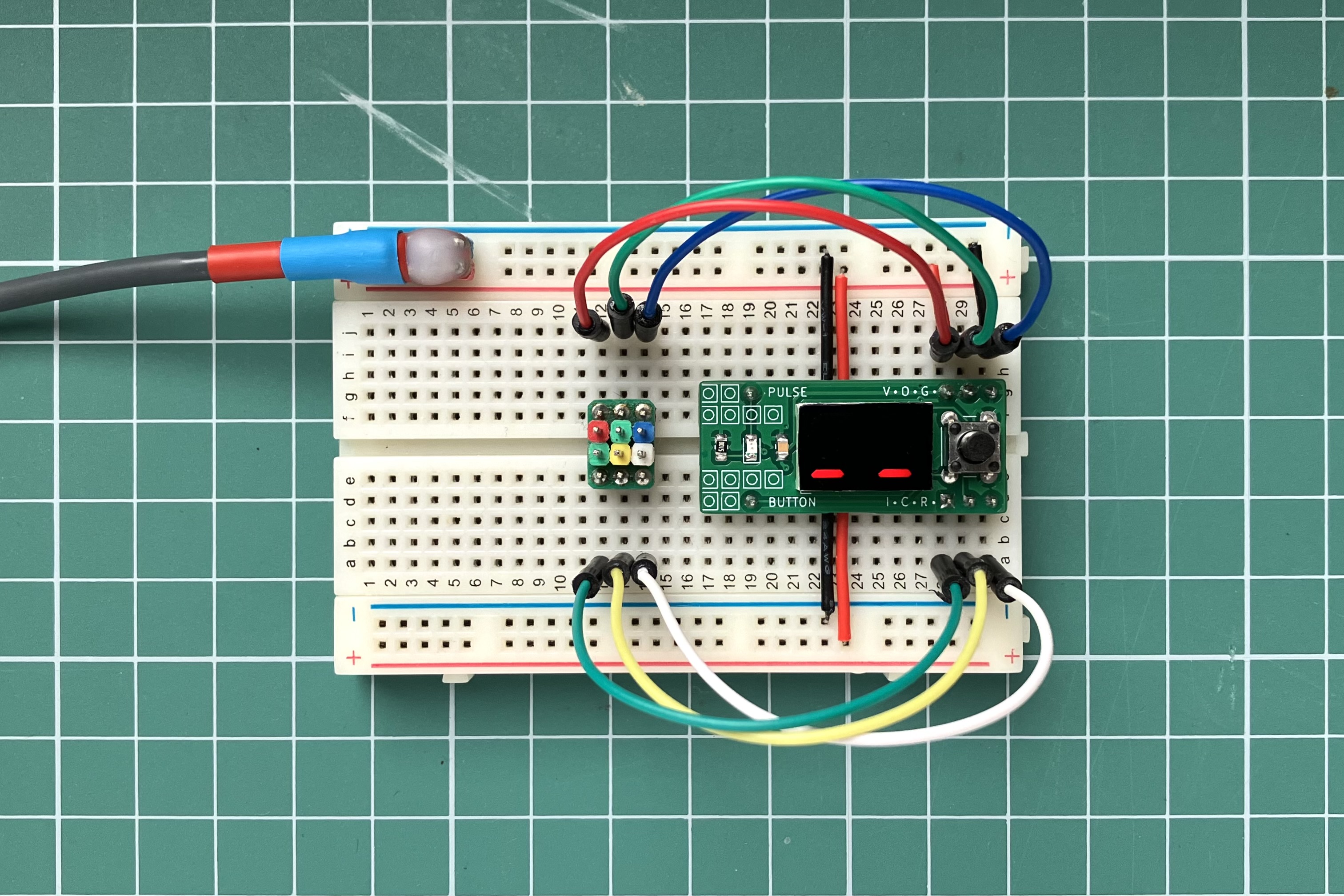
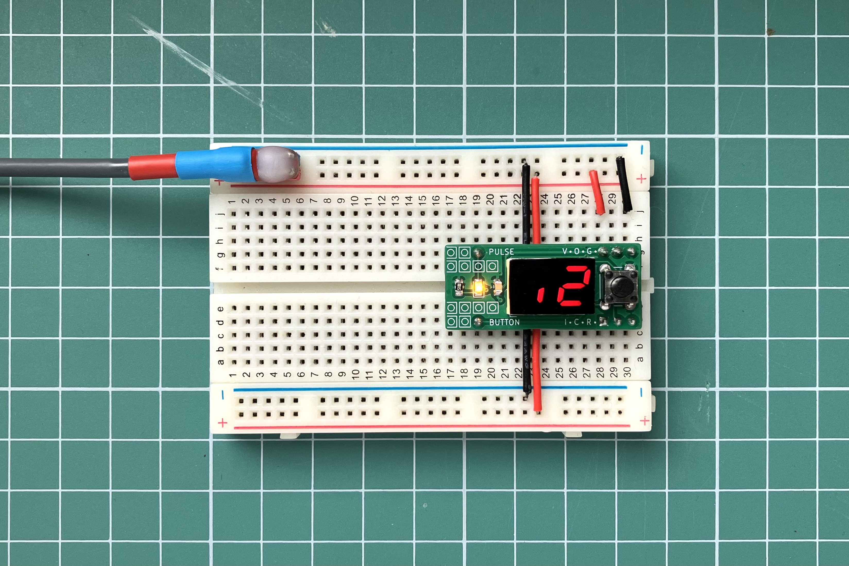
Use double click to change operating mode. In both modes an LED indicates a voltage level on the PULSE pin.
In manual mode the device operates as a debounced button. The seven segment display indicates a voltage level on the PULSE pin (like an oscilloscope).
In automatic pulse mode the display indicates a current pulse frequency. You could bear though frequencies with a long button click.
| Qty | Value | Footprint | References |
|---|---|---|---|
| 7 | 330 | Resistor_SMD:R_0805_2012Metric_Pad1.20x1.40mm_HandSolder | R1, R2, R3, R4, R5, R6, R7 |
| 1 | 100nF | Capacitor_SMD:C_0805_2012Metric_Pad1.18x1.45mm_HandSolder | C1 |
| 1 | 2281BS | Display_7Segment:Sx39-1xxxxx | U2 |
| 1 | 510 | Resistor_SMD:R_0805_2012Metric_Pad1.20x1.40mm_HandSolder | R9 |
| 1 | ATtiny24 | Package_SO:SOIC-14_3.9x8.7mm_P1.27mm | U1 |
| 1 | Conn_Button | Connector_PinHeader_2.54mm:PinHeader_1x01_P2.54mm_Vertical | J2 |
| 1 | Conn_ICSP.a | Connector_PinHeader_2.54mm:PinHeader_1x03_P2.54mm_Vertical | J3 |
| 1 | Conn_ICSP.b | Connector_PinHeader_2.54mm:PinHeader_1x03_P2.54mm_Vertical | J4 |
| 1 | Conn_Pulse | Connector_PinHeader_2.54mm:PinHeader_1x01_P2.54mm_Vertical | J1 |
| 1 | SW_Push | Button_Switch_THT:SW_PUSH_6mm_H5mm | SW1 |
| 1 | YELLOW | LED_SMD:LED_0805_2012Metric_Pad1.15x1.40mm_HandSolder | D1 |
It measures 35.8 × 15.7 mm and has 2 copper layers, 1.6 mm thick.
17 parts, built around the ATTINY24A-MF. The full list of its parts is on this page, with links to each part's symbol and footprint where PCBKit's library has them.
From the LeftyDeMilo/clock-pulse-generator repository on GitHub, at the commit this page was made from: the board is clock_pulse_generator_kicad_scheme/clock_pulse_generator_kicad_scheme.kicad_pcb and its schematic clock_pulse_generator_kicad_scheme/clock_pulse_generator_kicad_scheme.kicad_sch. PCBKit opens the board in the browser, with nothing to install.
Its repository states no licence, so its author keeps all rights: ask LeftyDeMilo before reusing the design.


hoglet67/RGBtoHDMI
Bare-metal Raspberry Pi project that provides pixel-perfect sampling of Retro Computer RGB/YUV video and conversion to HDMI


hackclub/OnBoard
💡 Join 1,000 teenagers and make your first PCB with a $100 grant!

DDeGonge/OS-ARM
This arm is not industrial and it will not be fast, but that is not my goal. But it will hopefully be a very nice looking arm fully capable of 6dof motion, cheap enough to keep it accessable but capable enough to…
