2 layers407 × 184 mm
TRS-80-Model I G E1
RetroStack/TRS-80-Model-I-G-E1
Hardware Replica of the TRS-80 Model I Revision G
230 parts57MIT

 lefticus/4bitalu5
This project is derived from my ECPE 2504 class that I took at Virginia Tech. The project was submitted on March 18, 1998.
4bitalu is an open-source printed circuit board by lefticus, from the lefticus/4bitalu repository on GitHub. It is a 2-layer board of 96.5 × 104.1 mm with 53 parts on 45 nets, routed with 779 tracks and 14 vias.
It is built around the 74LS00SC and 74LS175PC. Its parts include 20 diodes, 10 resistors, 8 capacitors, 8 ICs and 3 switches.


This project is derived from my ECPE 2504 class that I took at Virginia Tech. The project was submitted on March 18, 1998.
The goal of the class project was to create a "Nibble Slice ALU".
This was a project that had:
We were allowed to use 7400 series TTL logic chips
The projects were built on breadboards with jumpers, switches, chips provided by the university (no pictures of the original were taken)
Requirements:
8 instructions were required - but we have 16 possible opcodes. That means we ended up with an additional 8 "unintended" or "undocumented" OpCodes!
The original product requirements doc follows:
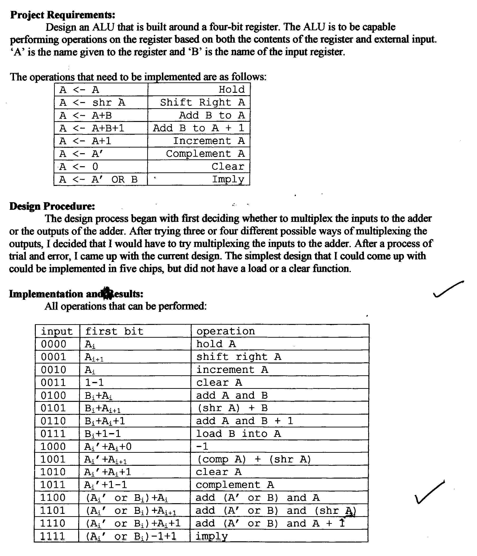
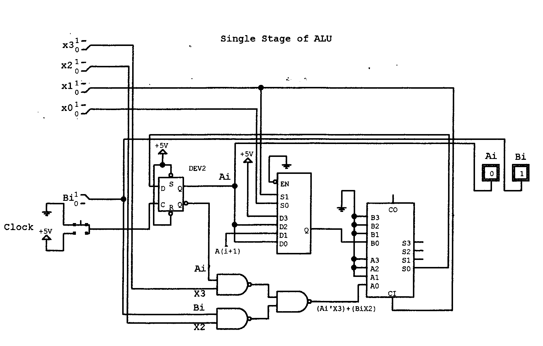
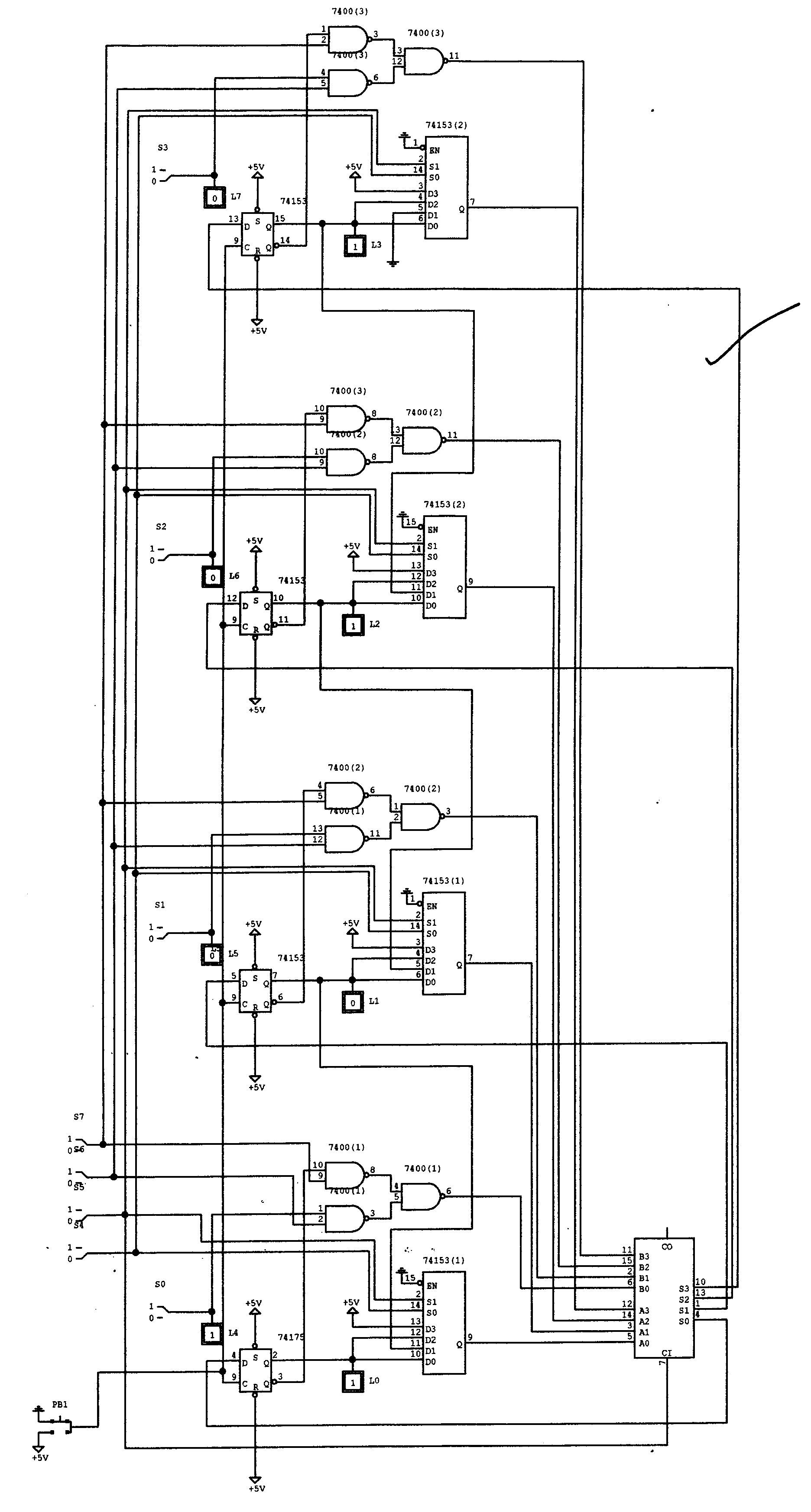
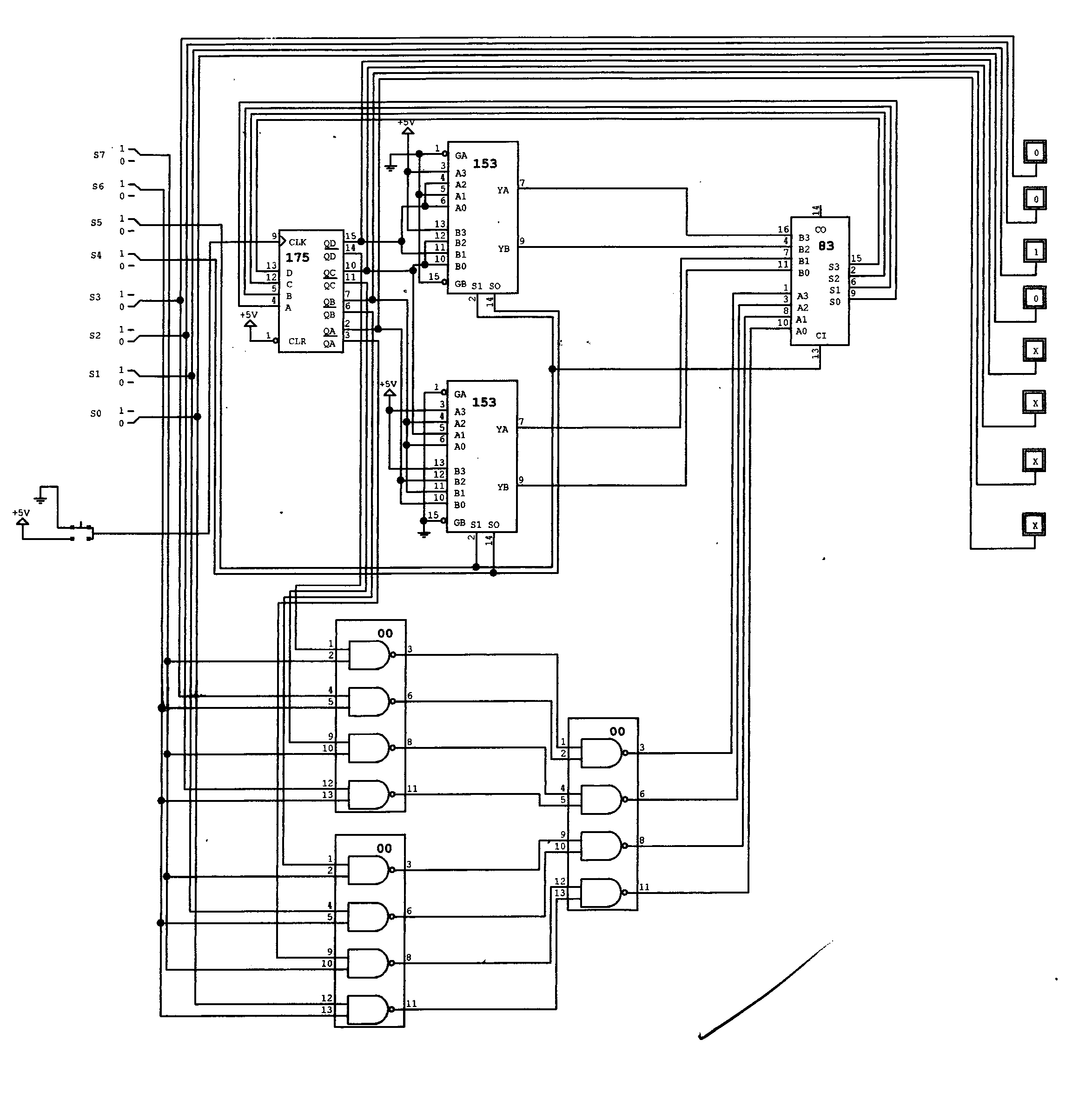
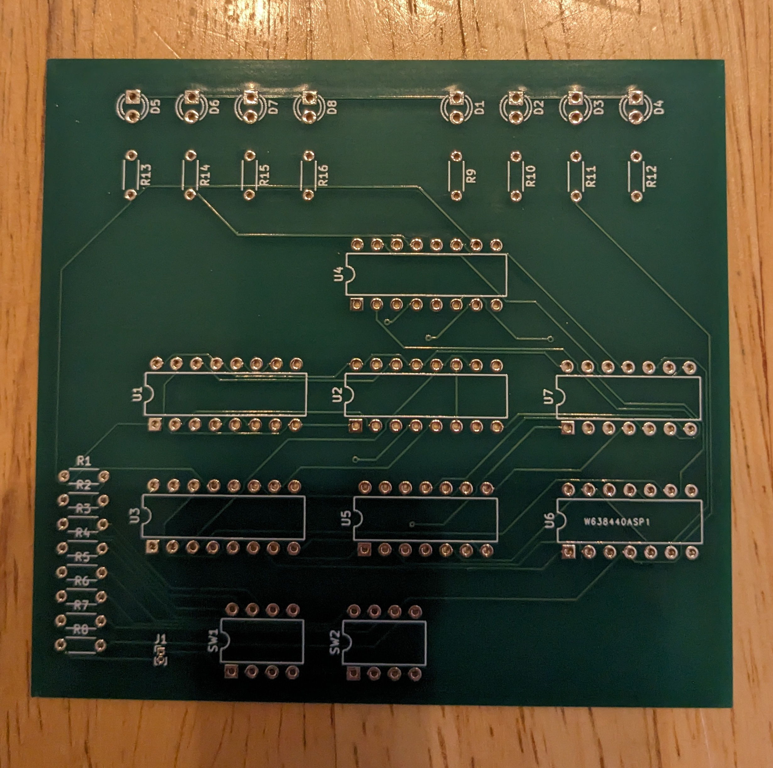
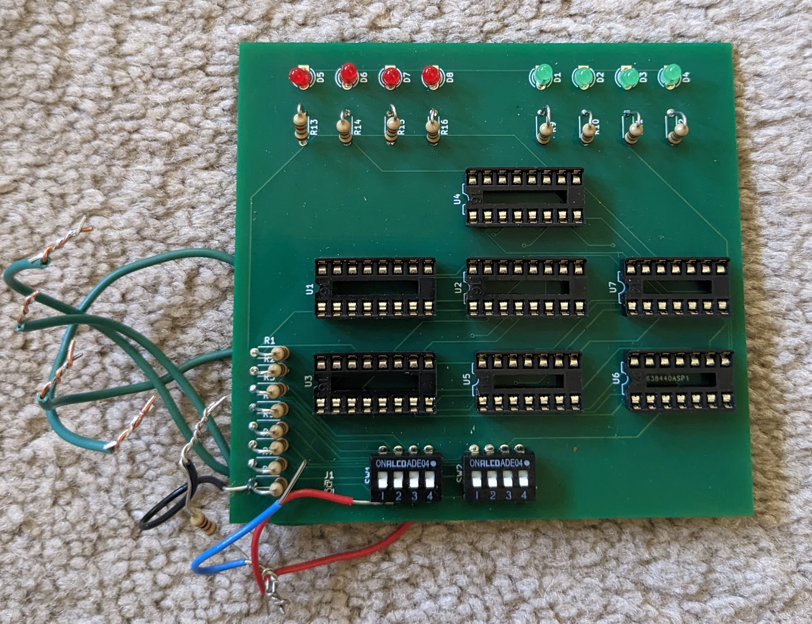
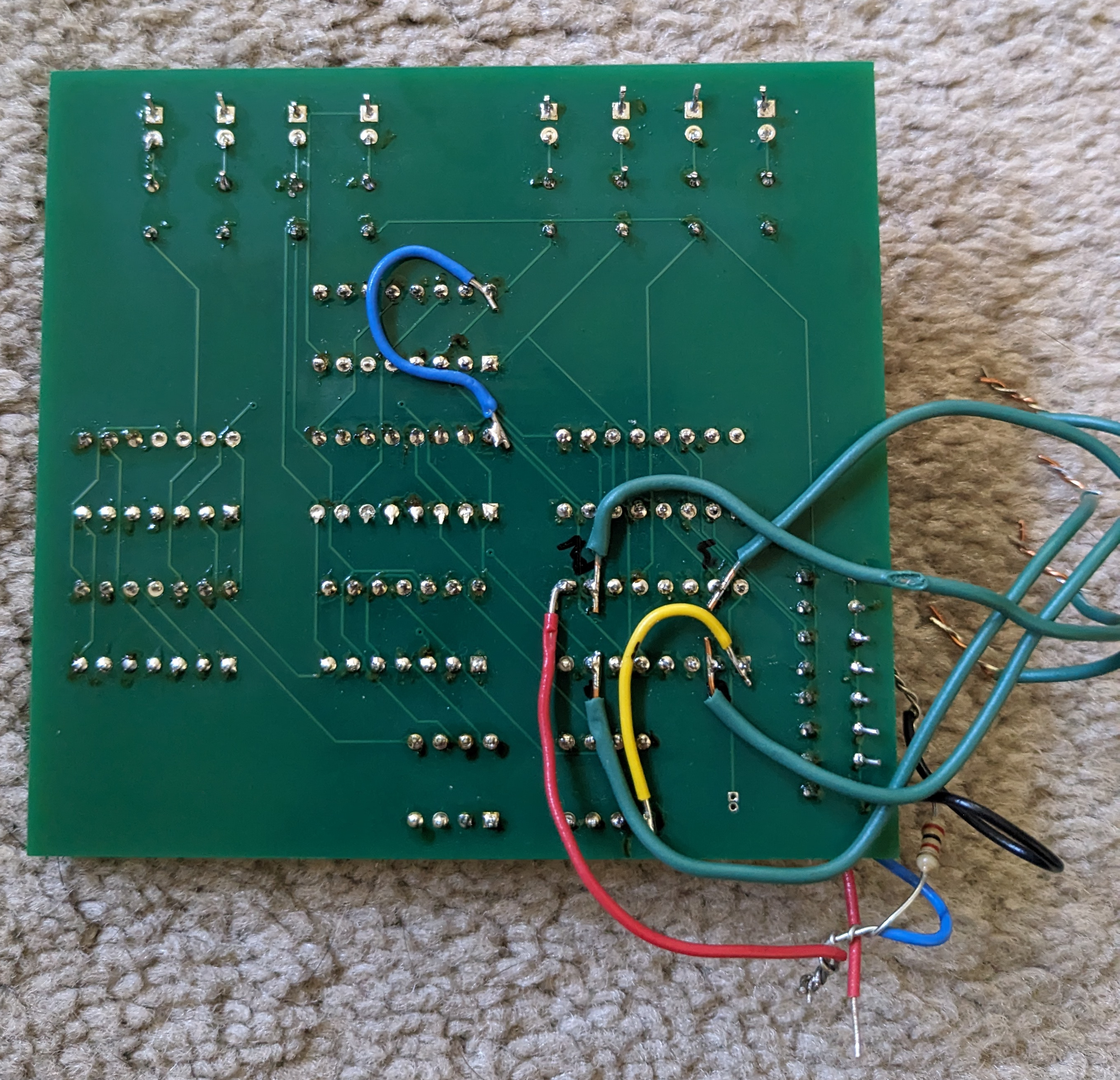
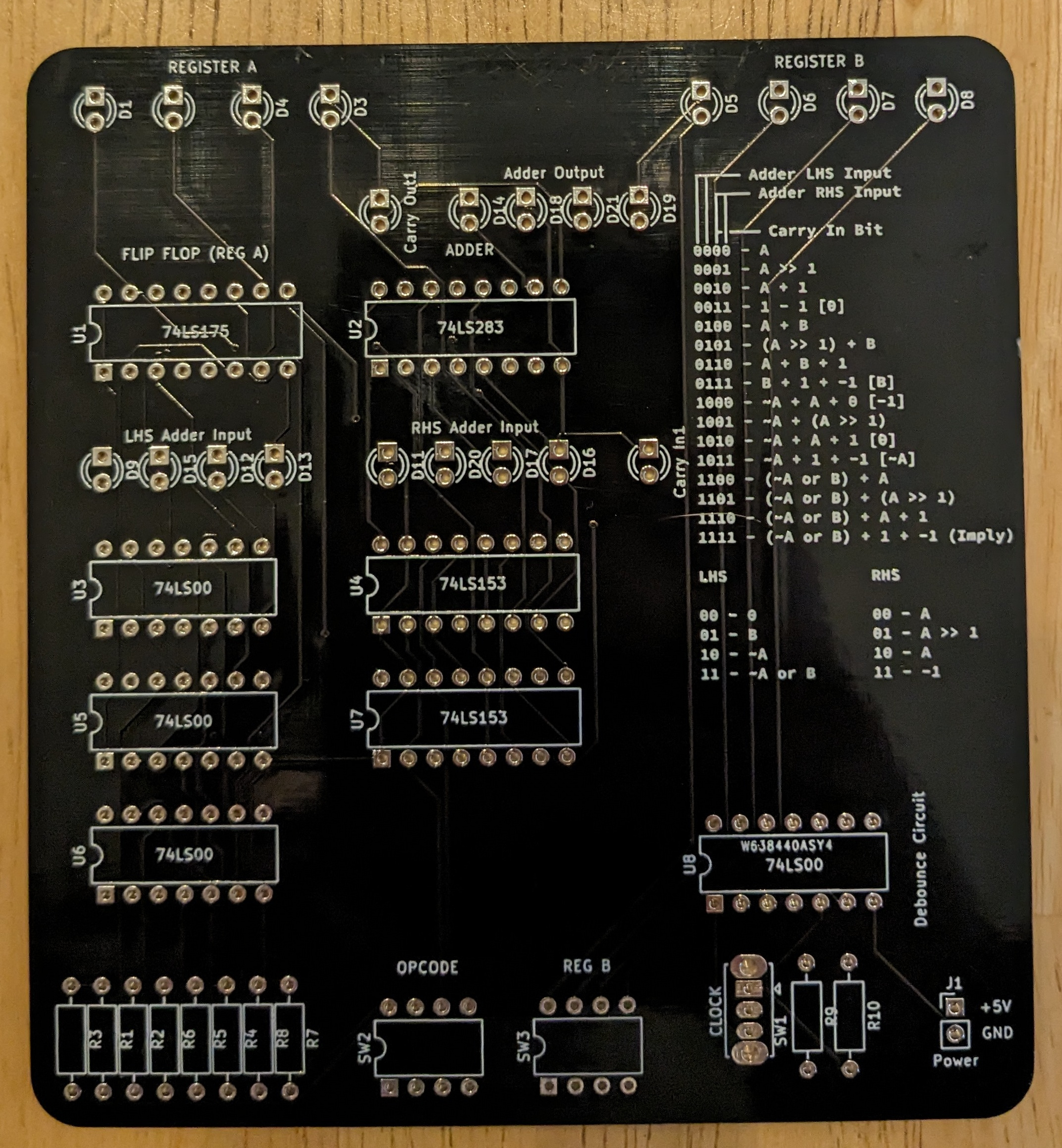
I decided 25 years later to try my hand at PCB design and to actually build this old project. This took 2 revisions:
These project files are all in KiCad format, if anyone wishes to fork / build their own / test this stuff out too
Rev 1 Empty
Rev 1 Front
Rev 1 Back with bodge wires
Rev 2 Empty
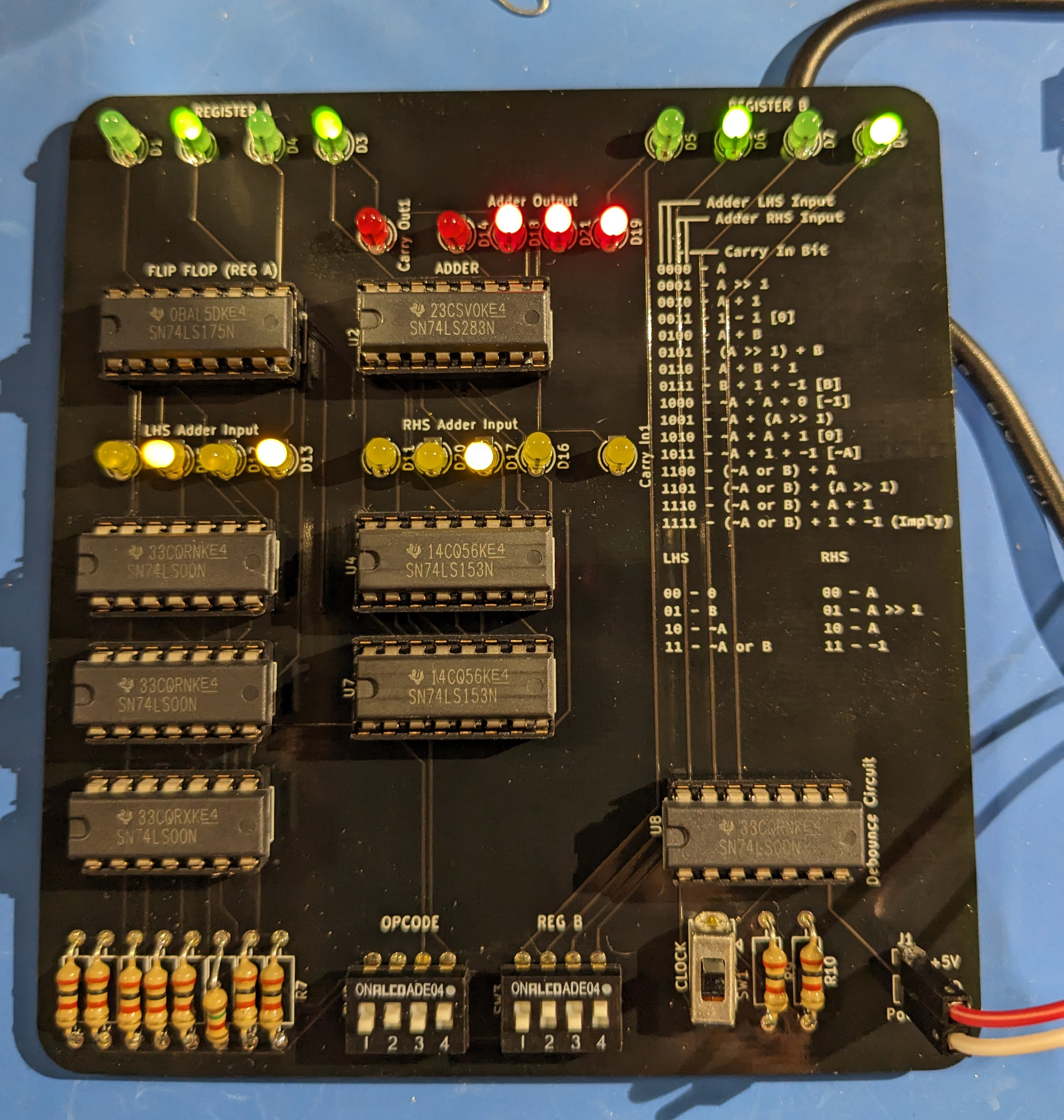
Rev 2 Running!
| Qty | Value | Footprint | References |
|---|---|---|---|
| 8 | .1uf | Capacitor_THT:C_Disc_D3.0mm_W1.6mm_P2.50mm | C1, C2, C3, C4, C5, C6, C7, C8 |
| 8 | 1k | Resistor_THT:R_Axial_DIN0207_L6.3mm_D2.5mm_P10.16mm_Horizontal | R1, R2, R3, R4, R5, R6, R7, R8 |
| 2 | 25k | Resistor_THT:R_Axial_DIN0207_L6.3mm_D2.5mm_P10.16mm_Horizontal | R9, R10 |
| 1 | 74LS00 | Package_DIP:DIP-14_W7.62mm | U8 |
| 1 | 74LS00 - Stage1 | Package_DIP:DIP-14_W7.62mm | U3 |
| 1 | 74LS00 Stage0-1 | Package_DIP:DIP-14_W7.62mm | U6 |
| 1 | 74LS00 Stage0-2 | Package_DIP:DIP-14_W7.62mm | U5 |
| 1 | 74LS153 - 0 | Package_DIP:DIP-16_W7.62mm | U4 |
| 1 | 74LS153 - 1 | Package_DIP:DIP-16_W7.62mm | U7 |
| 1 | 74LS175 | Package_DIP:DIP-16_W7.62mm | U1 |
| 1 | 74LS283 | Package_DIP:DIP-16_W7.62mm | U2 |
| 1 | CarryIn | LED_THT:LED_D3.0mm | Carry In1 |
| 1 | CarryOut | LED_THT:LED_D3.0mm | Carry Out1 |
| 1 | ClockState | LED_THT:LED_D3.0mm | ClockState1 |
| 1 | InBit0 | LED_THT:LED_D3.0mm | D8 |
| 1 | InBit1 | LED_THT:LED_D3.0mm | D7 |
| 1 | InBit2 | LED_THT:LED_D3.0mm | D6 |
| 1 | InBit3 | LED_THT:LED_D3.0mm | D5 |
| 1 | Input Value | Package_DIP:DIP-8_W7.62mm | SW3 |
| 1 | LHS0 | LED_THT:LED_D3.0mm | D13 |
| 1 | LHS1 | LED_THT:LED_D3.0mm | D12 |
| 1 | LHS2 | LED_THT:LED_D3.0mm | D15 |
| 1 | LHS3 | LED_THT:LED_D3.0mm | D9 |
| 1 | MidBit0 | LED_THT:LED_D3.0mm | D19 |
| 1 | MidBit1 | LED_THT:LED_D3.0mm | D21 |
| 1 | MidBit2 | LED_THT:LED_D3.0mm | D18 |
| 1 | MidBit3 | LED_THT:LED_D3.0mm | D14 |
| 1 | Opcode | Package_DIP:DIP-8_W7.62mm | SW2 |
| 1 | Power | Connector_PinHeader_2.54mm:PinHeader_1x02_P2.54mm_Vertical | J1 |
| 1 | RHS0 | LED_THT:LED_D3.0mm | D16 |
| 1 | RHS1 | LED_THT:LED_D3.0mm | D17 |
| 1 | RHS2 | LED_THT:LED_D3.0mm | D20 |
| 1 | RHS3 | LED_THT:LED_D3.0mm | D11 |
| 1 | RegBit0 | LED_THT:LED_D3.0mm | D3 |
| 1 | RegBit1 | LED_THT:LED_D3.0mm | D4 |
| 1 | RegBit2 | LED_THT:LED_D3.0mm | D2 |
| 1 | RegBit3 | LED_THT:LED_D3.0mm | D1 |
| 1 | SW_SPDT | Button_Switch_THT:SW_Slide_1P2T_CK_OS102011MS2Q | SW1 |
It measures 96.5 × 104.1 mm and has 2 copper layers, 1.6 mm thick.
53 parts, built around the 74LS00SC and 74LS175PC. The full list of its parts is on this page, with links to each part's symbol and footprint where PCBKit's library has them.
From the lefticus/4bitalu repository on GitHub, at the commit this page was made from: the board is 4bitalu/4bitalu.kicad_pcb and its schematic 4bitalu/4bitalu.kicad_sch. PCBKit opens the board in the browser, with nothing to install.
Its repository states no licence, so its author keeps all rights: ask lefticus before reusing the design.
RetroStack/TRS-80-Model-I-G-E1
Hardware Replica of the TRS-80 Model I Revision G

hkzlab/CGA_Redux
The Color Graphics Adapter Redux board is a more or less faithful clone of the original IBM CGA, based on the original schematics

btb/80ColumnCard
An Apple II 80-Column Card. Based on the Videx Videoterm

alvaroalea/plusD-clone
Schematic of a clone of the Disk Interface +D for the ZX Spectrum


misterblack1/zenith_zt1
Information gathered on the Zenith ZT-1 / ZT-10 / ZT-11 and ZTX/ZT-x-A variants