2 layers229.5 × 95.1 mm
Sweep high
davidphilipbarr/Sweep
Sweep - a small promicro based keyboard inspired by the Ferris.
55 parts2.1k

 laurivosandi/sumochip17
Sumorobot platform on top of CHIP board
Sumochip is an open-source printed circuit board by laurivosandi, from the laurivosandi/sumochip repository on GitHub, published under the MIT licence. It is a 2-layer board of 68.6 × 68.6 mm with 55 parts on 35 nets, routed with 205 tracks and 0 vias.
Its parts include 20 resistors, 11 connectors, 9 diodes and 6 transistors.
SumoCHIP is an extremely low-budget robotics platform based on CHIP single-board computer. SumoCHIP is designed for teaching soldering, electronics, programming and networking.
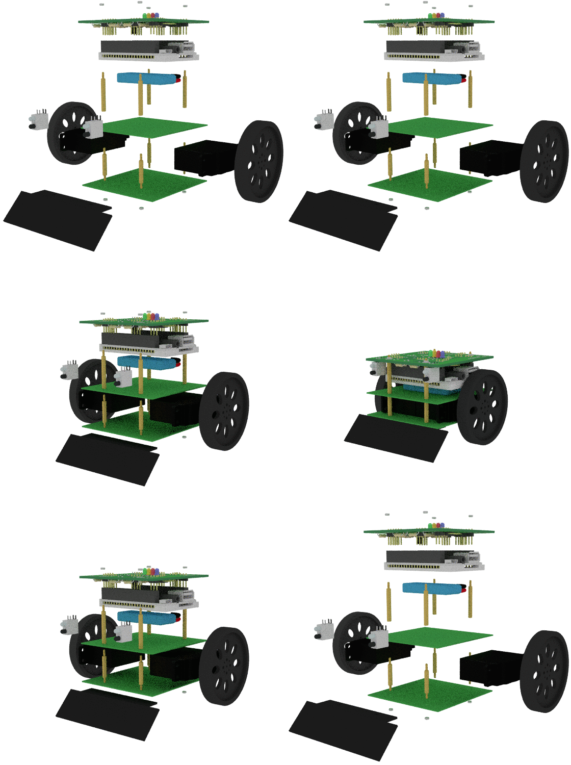


Bill of materials, instructions for building the robot and setting up the software are available here. Translations are very much welcome. See below how you can contribute!
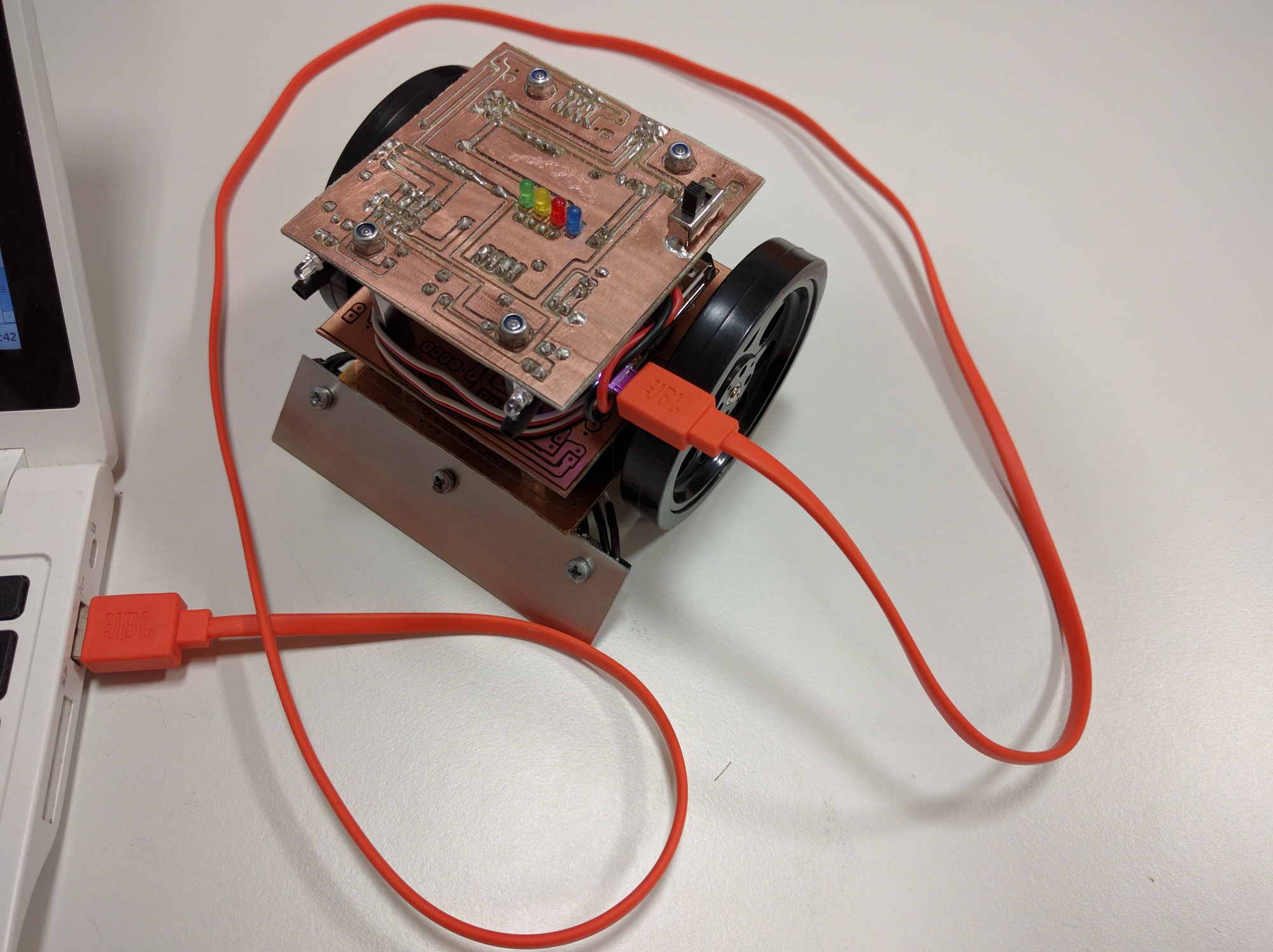
This is how the robot looks like once assembled:
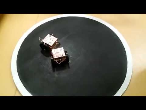
Here's a video of two sumorobots battling in the sumo ring:
Being completely open hardware you can order the components and assemble the robot yourself with the prices stated in the bill of materials page, expect to spend around 30 USD per robot. Robotics Club of Estonian IT College provides kits within EU which saves you the hassle of purchasing invidual components online.
| Description | Price |
|---|---|
| SumoCHIP PCB and solderable components only | 20 EUR + recommended donation |
| Everything except C.H.I.P. | 40 EUR + recommended donation |
| All in one batteries included kit | 50 EUR + recommended donation |
When ordering please specify whether you want PCB to be soldered or not, soldered board adds extra 10 EUR to the price. We can also ship custom configurations of components. Donations are used to renew the equipment of robotics club so we could continue doing cool stuff!
To order send us e-mail and we'll reply with an invoice PDF. Within EU standard SEPA payments are expected. Once payment is received the kits will be shipped with standard mail services once a week.
The current implementation is based on Python and Flask. In future we might add kernel module for generating fine grained PWM signals to achieve better timing granularity for servo motors.
Improvements and translations are very much welcome. The contents of this Git repository are published under very liberal MIT license. Just register an account here at GitHub and hit the Fork button in the top right corner, this shall make a copy of the source code repository under your GitHub account. Make the necessary modifications in your repository and once ready make a pull request to get your changes merged. All contributors shall be mentioned in the contributors list. We don't expect you to sign a contributor license agreement, but you should not forget that as this project is distributed under MIT license, third parties or even us are free to make commercial use of any of the repository's contents.
We are aware of following issues:
dialout group, log out from your desktop session and log in again. Otherwise your user account is unable to make use of the serial connection to CHIP, resulting in error cannot open /dev/ttyACM0.sumochip-test while the web interface is running in the background causes jerky behaviour, stop web interface first systemctl stop sumochip.Powering the robot:
If you have fried your AXP209, you can try to replace it with a new one. Damaged AXP209 can lead to battery drainage which can lead to irreversible battery damage or in extreme cases make the battery explode.
SumoCHIP is developed by Robotics Club of Estonian IT College

| Qty | Value | Footprint | References |
|---|---|---|---|
| 12 | 100 | Resistors_ThroughHole:Resistor_Horizontal_RM10mm | R3, R4, R5, R6, R10, R11, R12, R13, R14, R15, R16, R17 |
| 5 | Connect:1pin | Power, sw1, sw2, sw4, sw5 | |
| 5 | 100k | Resistors_ThroughHole:Resistor_Horizontal_RM10mm | R1, R2, R7, R8, R9 |
| 4 | Wire_Pads:SolderWirePad_single_2-5mmDrill | M1, M2, M3, M4 | |
| 4 | LED | LEDs:LED-3MM | D2, D3, D4, D5 |
| 3 | 10k | Resistors_ThroughHole:Resistor_Horizontal_RM10mm | R18, R19, R20 |
| 1 | 2N7000 | TO_SOT_Packages_THT:TO-92_Inline_Wide | Q6 |
| 1 | ActuatorsHeader | Pin_Headers:Pin_Header_Straight_2x03 | P2-3 |
| 1 | BatteryHeader | Pin_Headers:Pin_Header_Straight_1x03 | P4 |
| 1 | BatteryPins | Pin_Headers:Pin_Header_Angled_1x02 | P9 |
| 1 | DiagnosticHeader | Pin_Headers:Pin_Header_Straight_1x04 | P6 |
| 1 | EnemyBackLED | LEDs:LED-3MM | D9 |
| 1 | EnemyBackPhoto | LEDs:LED-3MM | Q5 |
| 1 | EnemyFrontLeftLED | LEDs:LED-3MM | D1 |
| 1 | EnemyFrontLeftPhoto | LEDs:LED-3MM | Q1 |
| 1 | EnemyFrontRightLED | LEDs:LED-3MM | D6 |
| 1 | EnemyFrontRightPhoto | LEDs:LED-3MM | Q2 |
| 1 | EnemyLeftLED | LEDs:LED-3MM | D7 |
| 1 | EnemyLeftPhoto | LEDs:LED-3MM | Q3 |
| 1 | EnemyRightLED | LEDs:LED-3MM | D8 |
| 1 | EnemyRightPhoto | LEDs:LED-3MM | Q4 |
| 1 | LineFollowLED | Pin_Headers:Pin_Header_Straight_2x03 | P13-15 |
| 1 | LineFollowPhoto | Pin_Headers:Pin_Header_Straight_2x03 | P10-12 |
| 1 | PowerHeader | Pin_Headers:Pin_Header_Straight_1x03 | P16 |
| 1 | SensorsHeader | Pin_Headers:Pin_Header_Straight_2x05 | P7-8 |
| 1 | SerialHeader | Pin_Headers:Pin_Header_Straight_1x03 | P1 |
| 1 | SerialPins | Pin_Headers:Pin_Header_Angled_1x03 | P5 |
| 1 | ServoPins | Pin_Headers:Pin_Header_Straight_2x03 | P17-18 |
It measures 68.6 × 68.6 mm and has 2 copper layers, 1.6 mm thick.
55 parts. The full list of its parts is on this page, with links to each part's symbol and footprint where PCBKit's library has them.
From the laurivosandi/sumochip repository on GitHub, at the commit this page was made from: the board is pcb/sumochip.kicad_pcb. PCBKit opens the board in the browser, with nothing to install.
Its repository publishes it under the MIT licence: you may reuse it on that licence's terms (keep the author's notice, and for a copyleft licence share your changes alike).
davidphilipbarr/Sweep
Sweep - a small promicro based keyboard inspired by the Ferris.

VoronDesign/Voron-Hardware
Cool Hardware designed by the Voron Design group

hackclub/OnBoard
💡 Join 1,000 teenagers and make your first PCB with a $100 grant!

lever-tech/flake
An open-source, wireless, split ergonomic keyboard designed to be productive, healthy, and enjoyable. [formerly Anywhy Flake]

jes/scamp-cpu
A homebrew 16-bit CPU with a homebrew Unix-like-ish operating system.

CRImier/MyKiCad
My KiCad boards. Can't be bothered uploading individually anymore, so here you go.

rgoulter/keyboard-labs
Repo with my PCB designs and keyboard firmware

dcpedit/dissatisfaction30
To get the PCB manufactured, upload dissat-pcb.zip to JLCPCB, select your desired PCB color while keeping all the other default options, and place your order (minimum 5).