2 layers103 × 30.5 mm

 laneboysrc/rc-brake-lights17
Easy-to-build light controller for RC cars that simulates realistic brake and reversing lights
Rc brake lights is an open-source printed circuit board by laneboysrc, from the laneboysrc/rc-brake-lights repository on GitHub, published under the MIT licence. It is a 2-layer board of 22 × 10 mm with 9 parts on 10 nets, routed with 32 tracks and 3 vias.
Its parts include 3 resistors, 2 connectors, 1 capacitor, 1 IC and 1 diode. It belongs with the 8051 (CH55x, STC, AT89) boards of this library.
This project is an easy-to-build light controller for Radio Controlled cars that simulates realistic brake and reversing lights.
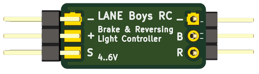
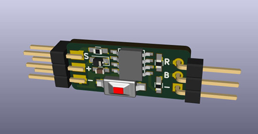
It hooks between your ESC and receiver.
The brake lights automatically turn on for a short, random time when the throttle goes to neutral. The reversing lights turn on when driving backwards.
The light controller supports various ESC modes to ensure the lights are in sync with the way your ESC controls the drive motor.
The aim of the project is to make it easy to build anyone with minimal electronics knowledge. If you are unable to build it yourself please contact laneboysrc@gmail.com; we'd be happy to sell you one.
If you are looking for more than just brake lights check out our full-featured DIY RC Light Controller.
The core of the light controller is the inexpensive STC STC15W104. It is a modern interpretation of the venerable 8051 MCU. This MCU was chosen due to its very low cost and because it can be programmed with an inexpensive USB-to-serial adapter, or using the serial port on a Raspberry Pi.
You can find the STC15W104 usually on eBay, AliExpress, Electrodragon, LCSC ...
Beside the MCU you need 3 resistors, a diode and a capacitor. The complete list of components can be found in the electronics/ folder
For convenience the schematics are available as PDF file.
Due to the small number of required components, the light controller can be easily built on a perfboard. The following image shows how to wire everything up:
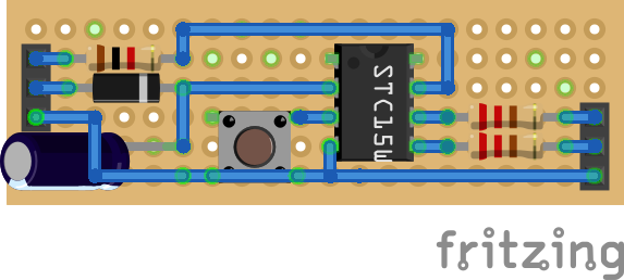
(The Fritzing source file for this drawing is provided in the fritzing/ folder)
If you plan to build several controllers it may be worth-while to order printed circuit boards. Gerber files for manufacturing PCBS are provided, as well as the KiCad source files. Note that the PCB uses SMD components rather than through-hole. Still, it is designed for hand-soldering.
You can find the pre-compiled firmware released as part of the project.
If you want to build or modify the firmware you will need SDCC and GNU Make.
To flash the firmware into the STC15W104, use STCGAL.
Follow the instructions at https://github.com/grigorig/stcgal#installation to install STCGAL. This programming tool for the STC MCU requires Python 3, and the Python 3 libraries pyserial and tqdm.
pip install pyserial tqdmConnect your USB-to-serial adapter to the RC-brake-lights controller as follows:
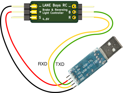
Do not connect + yet, only after starting STCGAL.
Download the firmware Intel-HEX file and execute STCGAL as follows:
python stcgal.py -t 12000 --option low_voltage_reset=true --option low_voltage_threshold=0 --option eeprom_lvd_inhibit=true -b 1200 -p COM7 rc-brake-lights.ihxImportant: Replace the COM port number with the one of your USB-to-serial adapter. In Windows consult the Device Manager to find out which port number to use.
Once started, STCGAL prompts you to power-cycle the circuit. Plug in + and STCGAL should find the MCU and program it. Your controller is now ready to use.
The Raspberry Pi has a serial port accessible on its GPIO pin-header, so we can use it directly for programming.
Connect the RC-brake-lights controller as follows:
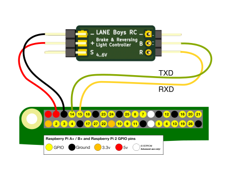
Do not connect + yet, only after starting STCGAL.
Download and unpack STCGAL:
wget https://github.com/grigorig/stcgal/archive/master.zip
unzip master.zip
Install the required Python 3 modules:
sudo apt install python3-serial python3-tqdmUse sudo raspi-config and go to Interface Options, then P6 Serial where you can disable log-in via the serial console, and enable the serial hardware:
Would you like a login shell to be accessible over serial? Select NO
Would you like the serial port hardware to be enabled? Select YES
After rebooting, download the firmware Intel-HEX file and execute STCGAL as follows:
python3 stcgal-master/stcgal.py -p /dev/ttyAMA0 -t 12000 --option low_voltage_reset=true --option low_voltage_threshold=0 --option eeprom_lvd_inhibit=true -b 1200 rc-brake-lights.ihxOnce started, STCGAL prompts you to power-cycle the MCU. Plug in + and STCGAL should find the MCU and program it. Your controller is now ready to use.
The light controller has two parallel connectors on the input side. Connect your ESC to one of the plugs and connect the TH input of the receiver with a male-to-male servo cable to the other plug.
The B output drives two red LEDs in parallel for the brake light function, the R output drives two white LEDs in parallel for the reversing light function.
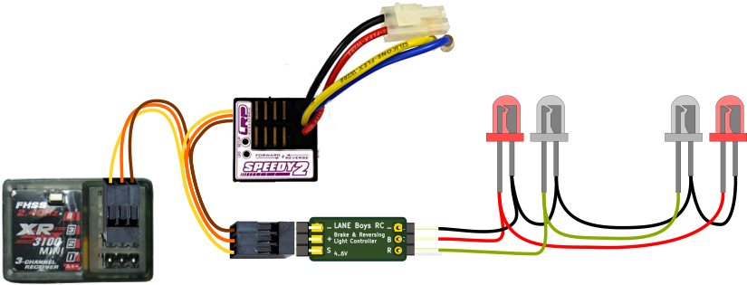
Depending on your RC system, out of the box the light controller may operate in the wrong direction (forward and backward reversed). To change this, press and hold the setup button on the light controller for 3 seconds. The LEDs will start flashing quickly.
Now move the throttle on the transmitter to the driving direction that would make the car move forward. When LEDs will go out and the light controller has now learned the correct direction of the throttle signal for forward. This setting is preserved, so you only have to do this once.
When it comes to brake function, ESC models behave differently. The light controller can be programmed for the specific behavior of your ESC.
To change the ESC mode, perform the following steps: Press and hold the setup button on the light controller. After 3 seconds, the LEDs will start to flash quickly. Press the setup button one more time. The light controller enters the ESC mode setting and flashes the current ESC mode number:
When driving forward and then immediately pushing the throttle to reverse, the ESC performs a brake function. The ESC only allows driving backwards if the ESC has remained in neutral position for a few seconds.
Example: The China 320A ESC, HPI SC-15WP
After going forward and then into reverse, the ESC always performs the brake function -- even if the throttle remained in neutral for a long time.
Example: Tamiya ESCs
Crawler ESC with drag brake, where the ESC switches from forward directly into reverse.
ESC in race mode where reversing is not allowed.
Press the setup button repeatedly until the desired ESC mode has been selected. Then press-and hold the setup button until the LEDs stop flashing. The ESC mode has now been persistently stored.
| Qty | Value | Footprint | References |
|---|---|---|---|
| 2 | 220 | Resistors_SMD:R_0603_HandSoldering | R2, R3 |
| 1 | 10u | Capacitors_SMD:C_0603_HandSoldering | C1 |
| 1 | 1N4148 | Diodes_SMD:D_SOD-323_HandSoldering | D1 |
| 1 | 1k | Resistors_SMD:R_0603_HandSoldering | R1 |
| 1 | LED | Pin_Headers:Pin_Header_Angled_1x03_Pitch2.54mm | J2 |
| 1 | STC15W104 | SMD_Packages:SOIC-8-N | U1 |
| 1 | Setup button | WLA:Tact_switch_SMD_6x3_6x2_5 | SW1 |
| 1 | TH | WLA:Pin_header_02x03_board_edge | J1 |


FrameworkComputer/ExpansionCards
Reference designs and documentation to create Expansion Cards for the Framework Laptop

VoronDesign/Voron-Hardware
Cool Hardware designed by the Voron Design group

hackclub/OnBoard
💡 Join 1,000 teenagers and make your first PCB with a $100 grant!


adamws/kicad-kbplacer
KiCad plugin for automatic keyboard's key placement and routing
It measures 22 × 10 mm and has 2 copper layers, 1.6 mm thick.
9 parts. The full list of its parts is on this page, with links to each part's symbol and footprint where PCBKit's library has them.
From the laneboysrc/rc-brake-lights repository on GitHub, at the commit this page was made from: the board is electronics/rc-brake-lights.kicad_pcb. PCBKit opens the board in the browser, with nothing to install.
Its repository publishes it under the MIT licence: you may reuse it on that licence's terms (keep the author's notice, and for a copyleft licence share your changes alike).