2 layers100 × 100 mm
Test jig
laneboysrc/rc-light-controller
Extensible RC car light controller with Web-based configuration tool
80 parts88MIT

 laneboysrc/rc-light-controller88
Extensible RC car light controller with Web-based configuration tool
Webusb programmer rev6 is an open-source printed circuit board by laneboysrc, from the laneboysrc/rc-light-controller repository on GitHub, published under the MIT licence. It is a 2-layer board of 38 × 20 mm with 18 parts on 31 nets, routed with 125 tracks and 14 vias.
It is built around the CH552G, TC118S and B5819WS. Its parts include 6 diodes, 5 resistors, 2 capacitors, 2 ICs and 2 connectors. It belongs with the radio and wireless and interfaces and adapters boards and the NXP (LPC, Kinetis, i.MX RT) and 8051 (CH55x, STC, AT89) boards of this library.


Realistic lighting of RC model cars using a standard 3-channel radio control system.
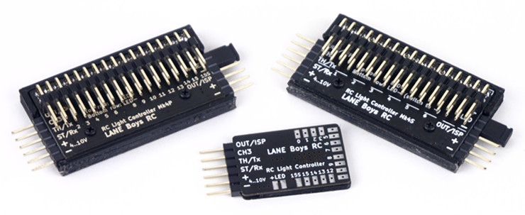
The light controller supports the following features, and more::
16 LED outputs, constant-current driven. Up to 20mA per output. Two light controllers can be cascaded for a total of 32 LED outputs. (Mk4 and Mk4P only)
1 high current non-dimmable switched output of up to 2A to drive a roof light bar (Mk4S: 9 non-dimmable switched outputs)
Parking, Low-beam, High-beam and a roof light bar can be switched on/off manually from the transmitter
Brake and Reversing lights are automatically controlled by monitoring the throttle channel. The brake lights now automatically turn on for a short, random time when the throttle goes to neutral.
Combined tail and brake light function in a single LED through controlling the brightness of the LED. (Mk4 and Mk4P only)
Indicators only come on when you want to. You have to stay in neutral for one seconds, then hold the steering left/right for one second before they engage. This way normal driving does not trigger the indicators.
Hazard lights can be switched on/off from the transmitter
Programmable output designed to drive a steering wheel or a figures head, or a gearbox servo
Automatic center and end-point adjustment for steering and throttle channels
16 LEDs can be driven by one light controller. Two controllers can be daisy-chained for up to 32 LEDs.
Light Programs for custom light animations like police lights, running lights ...
Simulation of incandescent lights and faulty ground wiring
Optional i-Bus compatible input
Optional Pre-Processor for easier wiring
Up to 3 AUX channels can control light functions when using the 5-channel Pre- Processor
All functions can be customized through a web browser
An introduction video can be found at:
You may also want to read the users guide to get a grasp of the full functionality of this light controller system.
(Die Bedieungsanleitung ist auch in Deutsch verfügbar)
Firmware and schematics for the different variants are included in this project.
Over the years, the light controller went through various iterations. The document doc/hardware-overview.md explains the history of development.
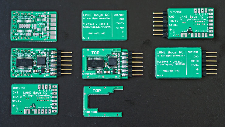
The current MK4 variant can drive 16 LEDs with a constant current. It utilises an inexpensive NXP ARM Cortex-M0 32-bit microcontroller. The main advantage of this design is that it can be fully configured through a web-based user interface. Firmware and configuration can be downloaded with a standard USB-to-serial converter, no proprietary tools required.
Not everyone is able to build circuit boards with tiny SMD components. If this applies to you please contact laneboysrc@gmail.com, we usually have a few fully built-up units in stock.
http://laneboysrc.blogspot.com/2012/07/diy-car-light-controller-for-3-channel.html
http://laneboysrc.blogspot.com/2013/09/diy-rc-light-controller-update.html
http://laneboysrc.blogspot.com/2012/12/pre-processor-for-diy-rc-light.html
http://laneboysrc.blogspot.com/2013/01/pre-processor-miniaturization.html
http://laneboysrc.blogspot.com/2014/07/ws2812-and-pl9823-led-power-consumption.html
http://laneboysrc.blogspot.com/2014/08/diy-rc-light-controller-with-ws2812b.html
| Qty | Value | Footprint | References |
|---|---|---|---|
| 3 | 1k8 | Resistor_SMD:R_0603_1608Metric | R1, R2, R3 |
| 2 | 5k1 | Resistor_SMD:R_0603_1608Metric | R4, R5 |
| 1 | 10u | Capacitor_SMD:C_0603_1608Metric | C1 |
| 1 | 1k | Resistor_SMD:R_Array_Convex_4x0603 | RN1 |
| 1 | 1u | Capacitor_SMD:C_0603_1608Metric | C2 |
| 1 | B5819WS | Diode_SMD:D_SOD-123 | D6 |
| 1 | BUSY | WLA_LED_reverse_mount:LED_0805_2012Metric_see_through | D3 |
| 1 | CH552G | Package_SO:SO-16_3.9x9.9mm_P1.27mm | U2 |
| 1 | ERROR | WLA_LED_reverse_mount:LED_0805_2012Metric_see_through | D4 |
| 1 | LC POWER | WLA_LED_reverse_mount:LED_0805_2012Metric_see_through | D1 |
| 1 | Light Controller | WLA_pinheader:PinHeader_1x06_P2.54mm_Flat | J1 |
| 1 | MCU POWER | WLA_LED_reverse_mount:LED_0805_2012Metric_see_through | D5 |
| 1 | OK | WLA_LED_reverse_mount:LED_0805_2012Metric_see_through | D2 |
| 1 | TC118S | Package_SO:SOP-8_3.9x4.9mm_P1.27mm | U1 |
| 1 | USB_C_Receptacle_USB2.0 | Connector_USB:USB_C_Receptacle_G-Switch_GT-USB-7010ASV | J2 |
It measures 38 × 20 mm and has 2 copper layers, 1 mm thick.
18 parts, built around the CH552G, TC118S and B5819WS. The full list of its parts is on this page, with links to each part's symbol and footprint where PCBKit's library has them.
From the laneboysrc/rc-light-controller repository on GitHub, at the commit this page was made from: the board is mk4-tlc5940-lpc812/tools/webusb-programmer/rev6-ch551-ch552-ch554/electronics/webusb-programmer-rev6.kicad_pcb and its schematic mk4-tlc5940-lpc812/electronics-pinheader/rev4/rc-light-controller-pinheader.kicad_sch. PCBKit opens the board in the browser, with nothing to install.
Its repository publishes it under the MIT licence: you may reuse it on that licence's terms (keep the author's notice, and for a copyleft licence share your changes alike).
laneboysrc/rc-light-controller
Extensible RC car light controller with Web-based configuration tool

laneboysrc/rc-light-controller
Extensible RC car light controller with Web-based configuration tool

laneboysrc/rc-light-controller
Extensible RC car light controller with Web-based configuration tool

laneboysrc/rc-light-controller
Extensible RC car light controller with Web-based configuration tool

laneboysrc/rc-light-controller
Extensible RC car light controller with Web-based configuration tool

laneboysrc/rc-light-controller
Extensible RC car light controller with Web-based configuration tool


ElectronPlant/beepy_rc
Hobby project to make a RC rover platform using spare RC parts.

RocketScientist26/Quadruped-Hardware
Main, Battery protection and Servo PCBs for Quadruped robot


