
2 layers35 × 50 mm

 lambdakb/keyboard-lk23m1
LK23M Numpad / Macropad
Lk23m pcb is an open-source printed circuit board by lambdakb, from the lambdakb/keyboard-lk23m repository on GitHub. It is a 2-layer board of 76.2 × 119.1 mm with 60 parts on 51 nets, routed with 386 tracks and 19 vias.
Its parts include 25 switches, 23 diodes, 4 capacitors, 1 IC and 1 connector. It belongs with the keyboards and input boards and the RP2040 and AVR (ATmega, ATtiny) boards of this library.



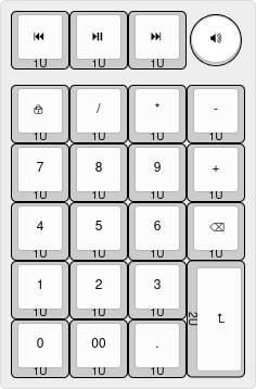
This keyboard has been designed as a standalone numpad with an extra top row to be used as a macro pad or media pad, as such, it can be configured in different ways when building it.
Here is the list of supported variations:
This allows for a number of configuration on the extra top row that can be used for a number of things. Each of these variations are supported in the Vial firmware under the Layout tab. See Vial Layout Options for more details.
Example #1 | Example #2 | Example #3 | Example #4 |
|---|---|---|---|
 |  |  |  |
This PCB can also be built as a wireless keyboard using a nice!nano microcontroller. See Wireless Support for more details on how to achieve this.
| PCB (Front) | PCB (Back) |
|---|---|
 |  |
The PCB has been designed in KiCad EDA 9.0 using the kicad-lkbd libraries and kbplacer.
You can preview the project files using KiCanvas directly in your browser and download the latest fabrication files for JLCPCB from the latest release.
The exported schematic is also available under output/schematics.
| Parameters | Value |
|---|---|
| Base Material | FR4 |
| Layers | 2 |
| Dimensions | 76.2 × 119.06 mm |
| PCB Thickness | 1.6 mm |
| PCB Color 1 | Black |
| Silkscreen | White |
| Surface Finish 2 | Lead Free HASL or ENIG |
| Copper Weight | 1 oz |
| Via Covering | Tented |
| Min Via Hole Size | 0.3 mm |
| Board Outline Tolerance | ± 0.2 mm |
The following JCLPCB specific options are used to serialize PCBs on order. An 8 × 8 mm silkscreen square was added to the PCB to allow for a 2D barcode to be added.
| Parameters | Value |
|---|---|
| Mark on PCB | 2D barcode (Serial Number) |
| - Printing | 2D barcode & Number |
| - Code Type | Data Matrix Code |
| - Prefix | LKBD_LK23M_v100 |
| - Unique Number | Remove |
| - Incrementing Number | YYMM01 (e.g.: 250300) |
| - 2D Barcode Size | 8 × 8 mm |
| - 2D Barcode Position | Specify Position |
Serial numbers are based on the current date using the YYMM01 format for its incrementing numbers. Orders in February 2025 would start then start it at 250300, making the final serial LKBD_LK23M_v100_250300.
| Plate (Top) | Plate (Bottom) | Bottom Case (Top) | Bottom Case (Top) |
|---|---|---|---|
 |  |  |  |
The FR4 case has also been designed in KiCad EDA 9.0 and consist of two PCBs, one for the switch plate and one for the bottom plate.
Use the same parameters present in PCB Order to order the plate and bottom PCB. For JLCPCB orders, you can select "Remove Mark" for the "Mark on PCB" option as there is no need to serialize the case itself. You can find the fabrication files in output/case/fr4/fabrication/jlcpcb.
If you prefer to fabricate them by any other mean (such as laser cut acrylic), you can download their board outlines as DXF in output/case/dxf.
| Part | Ref. | Quantity | Optional | Remarks |
|---|---|---|---|---|
| PCB | LK23M PCB | 1 | ❌ | See PCB section on how to order it. |
| Top Plate | FR4 Top Plate | 1 | ✅ | Optional if using an alternative case. |
| Bottom Plate | FR4 Bottom Plate | 1 | ✅ | Optional if using an alternative case. |
| Case Screws | M2 × 4 mm Low Profile Socket Head Screw (Hex) | 8 | ✅ | Optional if using an alternative case. Low profile hex head screws are recommended, but any head type should be compatible. Screws up to 8 mm in length should work. |
| Case Standoffs | M2 × 12 mm Brass Hex Standoff | 4 | ✅ | Optional if using an alternative case. Longer / shorter standoff could work depending on how the controller is mounted and if using a battery. |
| Pro Micro Controller | Arduino Pro Micro 5V, Adafruit KB2040 or nice!nano | 1 | ❌ | Supports various Pro Micro style controller (including RP2040 based ones) as well as the nice!nano for wireless builds. 3 |
| MCU Socket | DIP-24 Round Socket (Wide, 15.24 mm) | 1 | ✅ | Recommended to socket the controller, can be omitted if soldered directly. Compatibles pins are required such as dismantled LED strip male adapters. |
| Reset Push Button | DIP 2pin Momentary Push Button (6 × 3.5 mm) (THT) | 1 | ✅ | Used as a reset switch, can be omitted if you flash the controller before installing it or if the controller can be put in bootloader mode from any other means. |
| 1N418 Diodes | 1N4148W T4 SOD-323 (SMD) or 1N4148 DO-35 (THT) | 21-23 | ❌ | Only 21 diodes are needed if the OLED screen is installed. |
| Kailh Hot-Swap Sockets | CPG151101S11-16 (SMD) | 19 | ✅ | The top 4 keys can not be made hot-swappable due to size constraint and need to be soldered directly. All switches can be soldered directly to the PCB if preferred. |
| Key Switches | Any Cherry MX Compatible Switch | 19-23 | ❌ | Amount depends on the variant built, a two encoder OLED setup would require 2 EC12 encoder and 19 MX switches, while the key switches only variant needs 23. |
| 2U Stabilizer | Any standard 2U PCB mounted MX stabilizer | 1 | ✅ | Recommended for Enter key stability. |
| Rotary Encoder(s) | Any EC11 / EC12 style 5-pin Encoder | 0-2 | ✅ | Optional, can be installed in place of the top left and/or top right most switches. |
| 100nF Capacitor(s) | 1206 SMD Ceramic Capacitor (SMD) or 104 Ceramic Disk Capacitor (5 × 2.5mm) (THT) | 0-4 | ✅ | Two recommended per encoder for noise filtering. |
| 0.91" OLED Display | SSD1306 0.91" 128X32 OLED I²C Display Module | 0-1 | ✅ | Optional, replace the top middle two switches. |
| Power Slide Switch | PCM12SMTR (SMD) or MSK-12C02 (SMD) | 1 | ✅ | Only required for battery powered wireless builds. 3 |
| Battery Connector | JST-PH 2pin right-angle Male Connector | 1 | ✅ | Only needed for battery powered wireless builds if the battery is not soldered directly to the board (recommended). 3 |
| 3.7V Li-Po Battery | 603449 (1100 mAh) or 503450 (1000 mAh) 3.7V Li-Po Battery | 1 | ✅ | Only required for battery powered wireless builds, any 3.7 V (1 Cell) Li-Po battery slimmer than 8 mm with a JST-PH connector should work. 3 |
The pre-build firmware available in this repository are compiled using Vial (a fork of QMK allowing customization via a GUI).
As per the original license of both Vial and QMK, the firmware itself is licensed under the GPLv3 license and its source code is available at vial-qmk/keyboards/lambdakb/lk23m.
| Layer 0 | Layer 1 |
|---|---|
 |  |
| Default | Disable Left Encoder | Disable Right Encoder | OLED Screen in Center |
|---|---|---|---|
 |  |  |  |
Each of these options can be combined to match the physical layout of your build.
To add wireless support to this keyboard, you will need a controller that provides power input and a charging circuit between the top RAW and GND such as the nice!nano.
The PCB itself provides a way to attach a JST-PH connector as well as a slide switch for power management. This slide switch must be set to ON for the charging circuit to work.
This hasn't been extensively tested yet and should be considered experimental (no wireless firmware will be provided for now). The feature was added to the PCB as way for us to prototype a potential wireless keyboard.
This design is licensed under the Creative Commons Attribution-NonCommercial-ShareAlike 4.0 International License (CC BY-NC-SA 4.0).
You are free to use, share, and adapt the design for non-commercial purposes, provided that:
If you are a retailer or business interested in selling this design or products derived from it, I am open to granting commercial licenses on a case-by-case basis. Please feel free to contact me to discuss terms.
You can select any PCB color you want but some manufacturers such as JLCPCB may charge you more for uncommon combos (such as Blue PCB + ENIG Surface Finish). ↩
The "HASL (with lead)" option is extremely discouraged due to the risk of lead poisoning. We strongly recommend paying the premium for the "Lead Free HASL" option. ↩
See Wireless Support for more details. ↩ ↩2 ↩3 ↩4
| Qty | Value | Footprint | References |
|---|---|---|---|
| 23 | 1N4148 | LKBD_Common:Diode_SMD+THT_SOD123_DO35_P6.5mm | D1, D2, D10, D11, D12, D13, D14, D15, D16, D17, D18, D19, D20, D21, D22, D23 +7 |
| 19 | SW_Push | LKBD_KeySwitch:SW_MX_HotSwap_THT_sqSilk | SW5, SW6, SW10, SW11, SW12, SW13, SW14, SW15, SW16, SW17, SW18, SW19, SW20, SW21, SW22, SW23 +3 |
| 4 | 100nF | LKBD_Common:Capacitor_SMD+THT_1206_5.0x2.5mm_P5.00mm | C1, C2, C3, C4 |
| 4 | MountingHole_Pad | MountingHole:MountingHole_2.2mm_M2_ISO14580_Pad | H1, H2, H3, H4 |
| 2 | RotaryEncoder_Switch_MP | LKBD_KeySwitch:SW_MX_EC11_THT_sqSilk | SW1, SW4 |
| 2 | SW_Push | LKBD_KeySwitch:SW_MX_THT_sqSilk | SW2, SW3 |
| 1 | Conn_01x02 | Connector_JST:JST_PH_S2B-PH-K_1x02_P2.00mm_Horizontal | J1 |
| 1 | OLED_I2C_SSD1306 | LKBD_OLED:OLED_SSD1306_128x32_0.91inch_I2C_btmSilk | OL1 |
| 1 | ProMicro_RP2040 | LKBD_MCU:MCU_KB2040_DIP-24_Socket_Reverse | U1 |
| 1 | SW_Push | LKBD_Common:SW_Push_1P1T_6x3.5mm | SW24 |
| 1 | SW_SPST | Button_Switch_SMD:SW_SPDT_PCM12 | SW25 |
| 1 | Stabilizer_MX_2U | LKBD_StabMX:Stabilizer_MX_2U | STAB23 |


sd2psx/pcb
The PCB must be produced in 0.8mm thickness. Production files are provided under the "Releases" tab. These do not include the through-hole OLED module.


BitDogLab/BitDogLab
Open-source educational hardware for embedded systems, programming, electronics, and physical computing.
It measures 76.2 × 119.1 mm and has 2 copper layers, 1.6 mm thick.
60 parts. The full list of its parts is on this page, with links to each part's symbol and footprint where PCBKit's library has them.
From the lambdakb/keyboard-lk23m repository on GitHub, at the commit this page was made from: the board is pcb/lk23m-pcb.kicad_pcb and its schematic pcb/lk23m-pcb.kicad_sch. PCBKit opens the board in the browser, with nothing to install.
Its repository states no licence, so its author keeps all rights: ask lambdakb before reusing the design.