2 layers30.3 × 33 mm

 labodj/resol-vbus-interface
Isolated RESOL VBus RX/TX interface for ESPHome: KiCad Rev E prototype, BOM and fabrication files
Resol VBus RevE is an open-source printed circuit board by labodj, from the labodj/resol-vbus-interface repository on GitHub. It is a 2-layer board of 64 × 50 mm with 51 parts on 32 nets, routed with 206 tracks and 182 vias.
It is built around the R05CTE05S-CT, ISO7221ADR-HX and MAX809TEUR+T, with the MIC5235-3.3YM5-TR, TS391RIYLT and CC0805KRX7R9BB104 among its other parts. Its parts include 13 capacitors, 12 resistors, 7 ICs, 3 diodes and 2 connectors. It belongs with the home automation and IoT boards of this library.


I designed this board to connect my RESOL DeltaSol CS Plus solar controller to ESPHome and Home Assistant, with hardware for both receiving and transmitting VBus messages.
The board takes a socketed LOLIN D1 mini or LOLIN S3 Mini and runs from 5 V. An isolated DC/DC converter and digital isolator keep the VBus side electrically separate from the ESP and its USB connection.
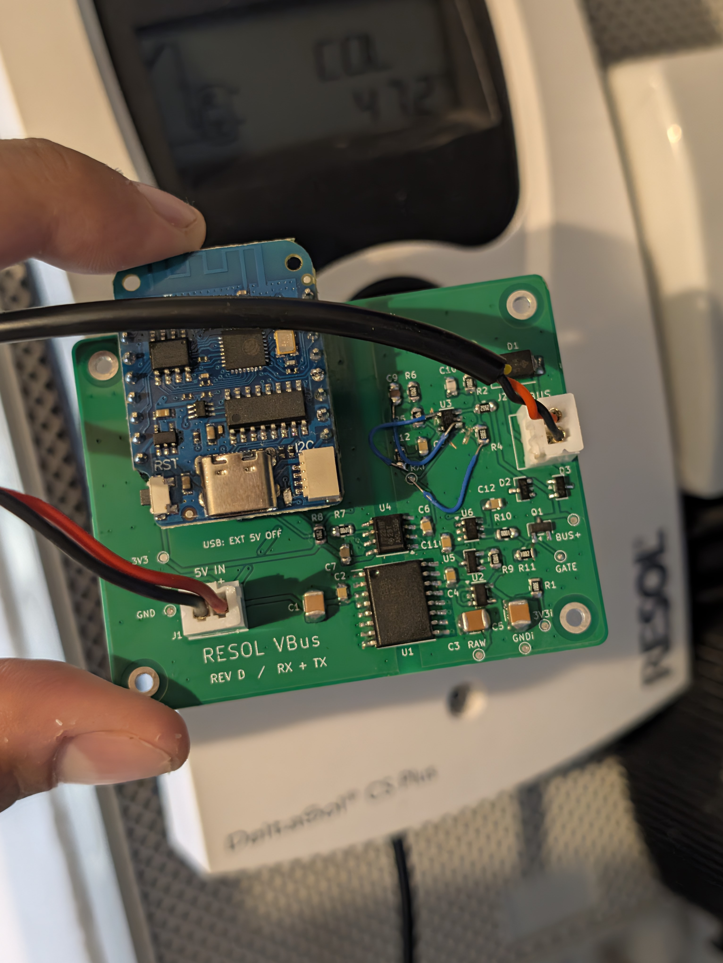
My assembled prototype connected to the solar controller. This is an earlier revision that needed a small wiring rework; the published design files are Rev E.
J1 is the 5 V input; J2 is VBus. The connectors are identical, so label the
cables. Use either USB power or external 5 V, never both at once. Keep
GND and GND_ISO separate. This is a low-voltage interface, not a mains input.
The target controller is a DeltaSol CS Plus running firmware 1.11, with an approximately 20 cm VBus cable.
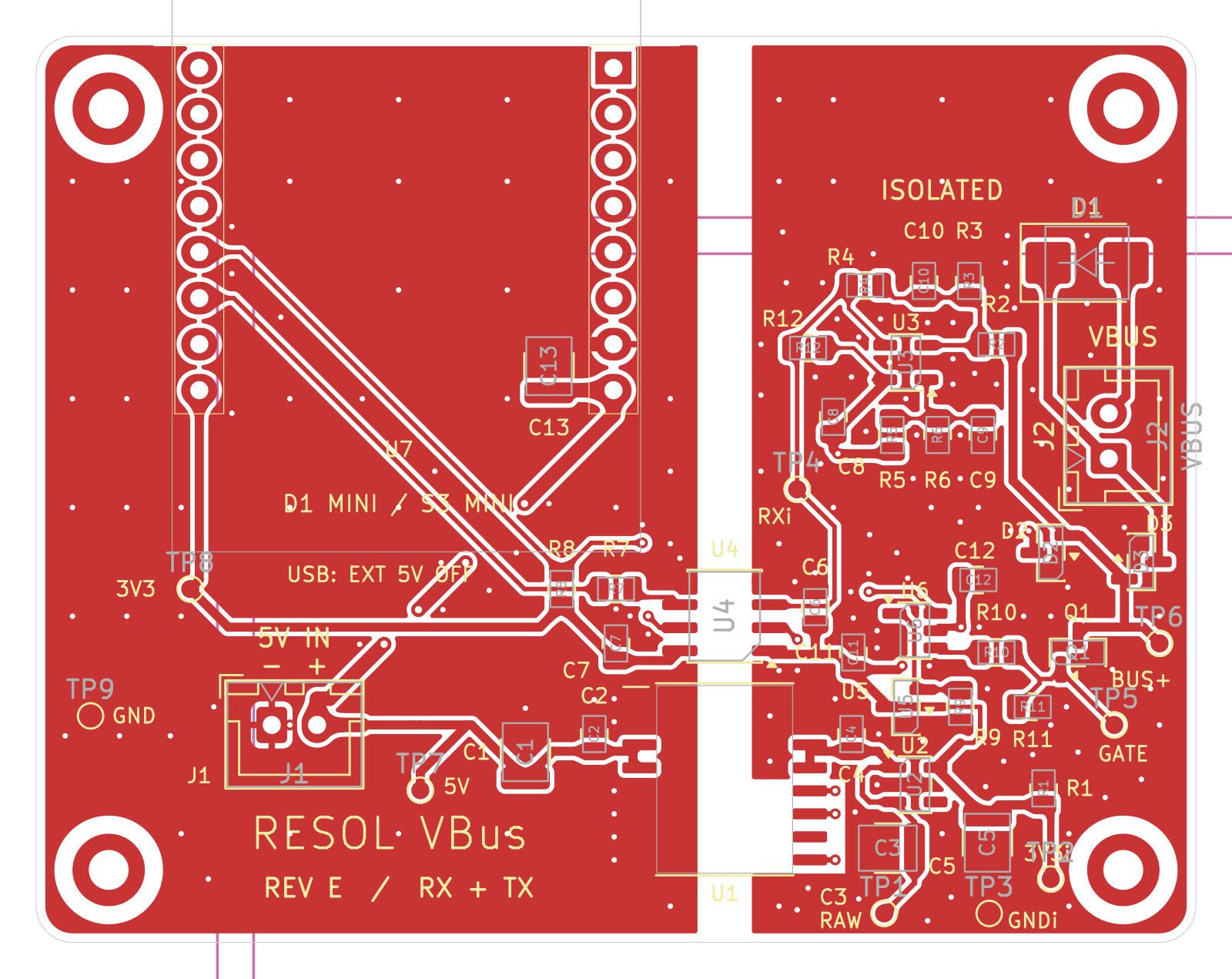
Rev E is a prototype: its CAD checks pass, but I have not yet assembled or bench-tested this revision. Other controllers, longer cables and the S3 Mini need their own tests. See validation for the checks and remaining limits. The Rev E layout below is a CAD view.
VBus uses UART at 9600 baud, 8N1, non-inverted. TX must idle HIGH; driving it LOW enables the bus sink when the isolated supply is ready. Firmware must wait for a bus grant before transmitting.
| Module | RX GPIO | TX GPIO | Rev E status |
|---|---|---|---|
| LOLIN D1 mini v4.0.0 (ESP8266) | 13 | 12 | Bench testing pending |
| LOLIN S3 Mini v1.0.0 | 11 | 13 | Not yet physically tested |
I am developing the ESPHome TX support separately. This repository contains the hardware, not a ready-to-flash firmware image. It does not imply that the standard ESPHome VBus component already supports transmitting settings.
Install KiCad 10 or newer with its standard libraries and open the .kicad_pro
file. Project libraries use relative paths. The optional RECOM 3D model is not
included; a missing model affects the 3D view only. See third-party notices.
The maintenance notes explain test-point exclusions and the checks to run after changes.
My original design drew on the ESPHome VBus documentation and FatBeard's VBus PCB project. This is an independent project, without endorsement by RESOL, ESPHome or LOLIN. Their names and trademarks remain theirs.
Original hardware: CERN-OHL-P-2.0; documentation: CC-BY-4.0; scripts: MIT. KiCad library data retains CC-BY-SA-4.0 with the KiCad library exception. See LICENSE.md and third-party notices.
| Qty | Value | Footprint | References |
|---|---|---|---|
| 7 | 100n | Capacitor_SMD:C_0805_2012Metric | C2, C4, C6, C7, C8, C11, C12 |
| 5 | 10k | Resistor_SMD:R_0805_2012Metric | R3, R6, R8, R11, R12 |
| 4 | 22u / 25V | Capacitor_SMD:C_1210_3225Metric | C1, C3, C5, C13 |
| 4 | M2 / 2.2 mm PTH | MountingHole_2.2mm_M2_Plated_Isolated | H1, H2, H3, H4 |
| 2 | 100R | Resistor_SMD:R_0805_2012Metric | R7, R10 |
| 2 | BAT54S | Package_TO_SOT_SMD:SOT-23 | D2, D3 |
| 1 | +3V3_ISO | TestPoint:TestPoint_Pad_D1.0mm | TP2 |
| 1 | +3V3_MCU | TestPoint:TestPoint_Pad_D1.0mm | TP8 |
| 1 | +5V | TestPoint:TestPoint_Pad_D1.0mm | TP7 |
| 1 | 100k | Resistor_SMD:R_0805_2012Metric | R9 |
| 1 | 220p C0G 50V | Capacitor_SMD:C_0805_2012Metric | C10 |
| 1 | 25k5 | Resistor_SMD:R_0805_2012Metric | R2 |
| 1 | 330k | Resistor_SMD:R_0805_2012Metric | R4 |
| 1 | 3k00 | Resistor_SMD:R_0805_2012Metric | R1 |
| 1 | 43k | Resistor_SMD:R_0805_2012Metric | R5 |
| 1 | 4n7 C0G 100V | Capacitor_SMD:C_0805_2012Metric | C9 |
| 1 | D1 mini / S3 | ResolVBusD:Wemos_D1_mini_2x08 | U7 |
| 1 | EXTERNAL 5 V | Connector_JST:JST_XH_B2B-XH-A_1x02_P2.50mm_Vertical | J1 |
| 1 | GND | TestPoint:TestPoint_Pad_D1.0mm | TP9 |
| 1 | GND_ISO | TestPoint:TestPoint_Pad_D1.0mm | TP3 |
| 1 | ISO7221ADR | Package_SO:SOIC-8_3.9x4.9mm_P1.27mm | U4 |
| 1 | MAX809TEUR+T | Package_TO_SOT_SMD:SOT-23 | U5 |
| 1 | MIC5235-3.3YM5-TR | Package_TO_SOT_SMD:SOT-23-5 | U2 |
| 1 | NTR4003NT3G | Package_TO_SOT_SMD:SOT-23 | Q1 |
| 1 | R05CTE05S-CT | ResolVBusD:RECOM_R05CTE05S | U1 |
| 1 | RX_ISO | TestPoint:TestPoint_Pad_D1.0mm | TP4 |
| 1 | SMBJ12CA | Diode_SMD:D_SMB | D1 |
| 1 | SN74AUP1G97DBVR | Package_TO_SOT_SMD:SOT-23-6 | U6 |
| 1 | TS391RIYLT | Package_TO_SOT_SMD:SOT-23-5 | U3 |
| 1 | TX_GATE | TestPoint:TestPoint_Pad_D1.0mm | TP5 |
| 1 | VBUS | Connector_JST:JST_XH_B2B-XH-A_1x02_P2.50mm_Vertical | J2 |
| 1 | VBUS_RECT | TestPoint:TestPoint_Pad_D1.0mm | TP6 |
| 1 | VISO_RAW | TestPoint:TestPoint_Pad_D1.0mm | TP1 |
It measures 64 × 50 mm and has 2 copper layers, 1.6 mm thick.
51 parts, built around the R05CTE05S-CT, ISO7221ADR-HX, MAX809TEUR+T and MIC5235-3.3YM5-TR. The full list of its parts is on this page, with links to each part's symbol and footprint where PCBKit's library has them.
From the labodj/resol-vbus-interface repository on GitHub, at the commit this page was made from: the board is hardware/rev-e/Resol_VBus_RevE.kicad_pcb and its schematic hardware/rev-e/Resol_VBus_RevE.kicad_sch. PCBKit opens the board in the browser, with nothing to install.
Its repository states no licence, so its author keeps all rights: ask labodj before reusing the design.

C12isme945/BioSmartSense-IoT
Portable IoT Electrochemical Biosensor & Edge AI Platform for Real-Time Water Quality & Bio-Diagnostics (Hyperbloom September Hackathon 2026)


devkyber/PCB
AI-assisted PCB engineering for native KiCad: source evidence, scoped changes, checked previews, human review, and reproducible release packages.

mahmoud-elghamry/thermocouple
This directory is a self-contained KiCad 10 project. It does not share files with, and must not be confused with, the single-channel board in hardware/single-channel/.


JosueHerrera05/Josue_Herrera_Electiva_2026_C2
Repositorio Electíva Diseño Mecatrónico 2026-C2

MukeshSethy/micromouse-runner
This is my repo for the first version of full size micromouse development.