2 layers18.5 × 11.1 mm
Switch
byrantech/laptop
anyon_e, a highly integrated, high end, open source laptop. Attempt the impossible.
6 parts4.3kMIT

 kyo-ta04/Pico2ROMEmuCB6
An RP2350B Core Board -based ROM emulator(including clock, reset, and UART-USB)
Pico2ROMEmuCB1 is an open-source printed circuit board by kyo-ta04, from the kyo-ta04/Pico2ROMEmuCB repository on GitHub, published under the MIT licence. It is a 2-layer board of 17.8 × 40.6 mm with 6 parts on 33 nets, routed with 132 tracks and 5 vias.
Its parts include 3 connectors, 2 resistors and 1 diode. It belongs with the RP2350 boards of this library.
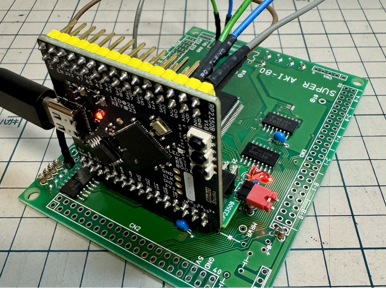 このプロジェクトは Pico2ROMEmuに RP2350B Core Boardを使用した簡単で高速なROMエミュレータです
English Readme
saki80mon041_const.c などの ROMデータ部分は https://github.com/yyhayami/saki80mon041 由来です。rom_basic_const.c などの ROM-BASIC 部分は saki80basic 由来です。
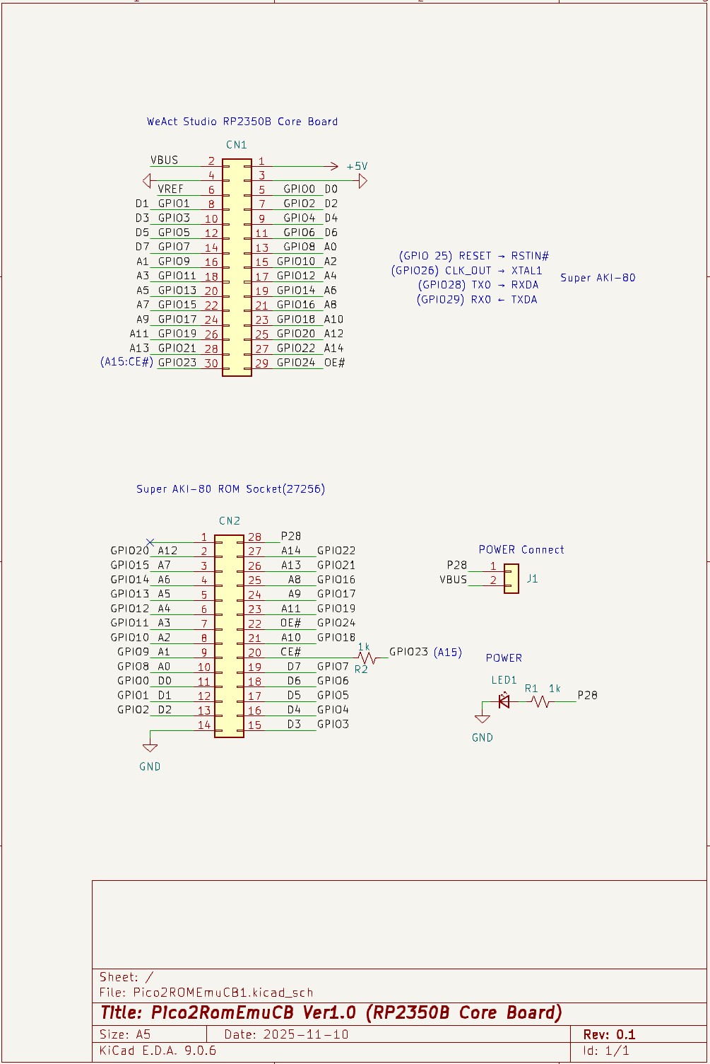 上記は回路図の画像です。
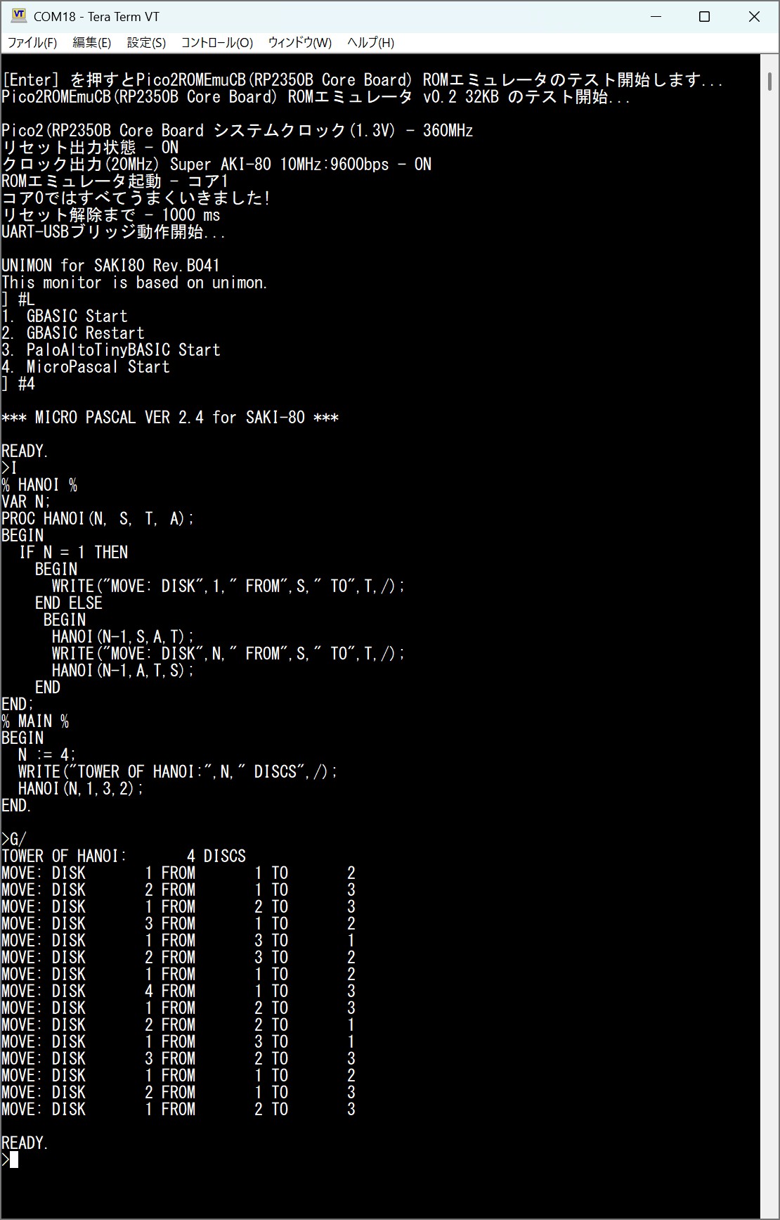 上記は saki80mon041.hex使用時の実行例画像です。
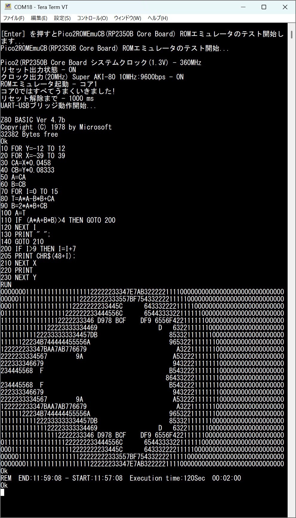 上記は SAKI80MB.HEX使用時の実行例画像です。
本ソフトウェアは現状のまま提供されます。いかなる損害についても作者は責任を負いません。
| Qty | Value | Footprint | References |
|---|---|---|---|
| 2 | 1k | Resistor_THT:R_Axial_DIN0204_L3.6mm_D1.6mm_P5.08mm_Horizontal | R1, R2 |
| 1 | Conn_01x02 | Connector_PinHeader_2.54mm:PinHeader_1x02_P2.54mm_Vertical | J1 |
| 1 | Conn_02x14_Counter_Clockwise | Package_DIP:DIP-28_W15.24mm_Socket | CN2 |
| 1 | Conn_02x15 | Connector_PinSocket_2.54mm:PinSocket_2x15_P2.54mm_Horizontal | CN1 |
| 1 | LED_Small | LED_THT:LED_D3.0mm | LED1 |
byrantech/laptop
anyon_e, a highly integrated, high end, open source laptop. Attempt the impossible.


Jcparkyn/dpoint
Open-source digital stylus using camera tracking and inertial measurements

VoronDesign/Voron-Hardware
Cool Hardware designed by the Voron Design group

hoglet67/RGBtoHDMI
Bare-metal Raspberry Pi project that provides pixel-perfect sampling of Retro Computer RGB/YUV video and conversion to HDMI

hackclub/OnBoard
💡 Join 1,000 teenagers and make your first PCB with a $100 grant!

Luos-io/luos_engine
Open-source and real-time orchestrator for cyber-physical-systems, to easily design, test and deploy embedded applications and digital twins.

It measures 17.8 × 40.6 mm and has 2 copper layers, 1.6 mm thick.
6 parts. The full list of its parts is on this page, with links to each part's symbol and footprint where PCBKit's library has them.
From the kyo-ta04/Pico2ROMEmuCB repository on GitHub, at the commit this page was made from: the board is PCB/Pico2ROMEmuCB1.kicad_pcb and its schematic PCB/Pico2ROMEmuCB1.kicad_sch. PCBKit opens the board in the browser, with nothing to install.
Its repository publishes it under the MIT licence: you may reuse it on that licence's terms (keep the author's notice, and for a copyleft licence share your changes alike).