2 layers60 × 30 mm
Controller
google/mozc-devices
Circuit diagrams and firmware source code for Gboard DIY keyboards
11 parts3kApache-2.0

 kvanderlaag/7Up-Extruder-PCB35
Replacement PCB for Creality Sprite/Sprite Pro Extruder PCB for Ender-3 series printers
SpritePCB is an open-source printed circuit board by kvanderlaag, from the kvanderlaag/7Up-Extruder-PCB repository on GitHub, published under the MIT licence. It is a 2-layer board of 54 × 50.5 mm with 11 parts on 15 nets, routed with 139 tracks and 14 vias.
Its parts include 7 connectors and 1 capacitor.
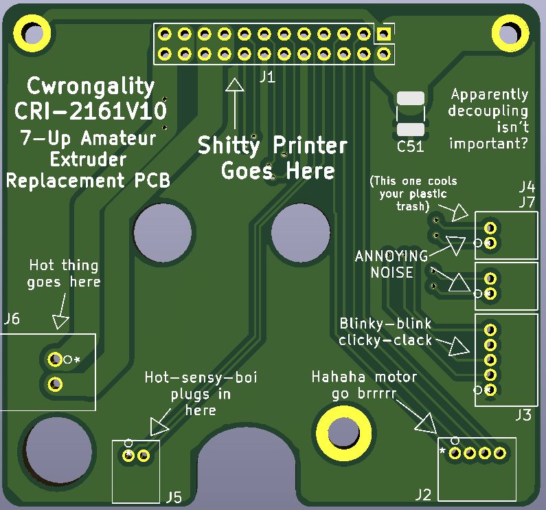
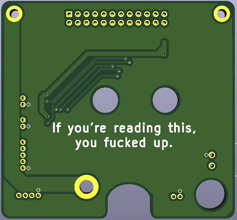
This is a replacement extruder/toolhead PCB for Creality Sprite/Sprite Pro Extruder PCB for Ender-3 series printers -- the Ender-3 S1, Ender-3 S1 Pro, Ender-3 S1 Plus, which all come with a Sprite direct drive extruder out of the box, or an Ender-3, Ender-3 Pro, or Ender-3 V2 that you've retrofitted with the Creality Sprite or Sprite Pro extruder kit.
While fumbling around behind my toolhead with a wrench to adjust the eccentric nut spacer on the X-axis, I managed to ram the wrench into the extruder connector, tearing it off the PCB and taking the solder pads and an appreciable amount of the traces connected to it with it. Naturally, I did this at the worst possible time, when I was printing parts necessary to get my other printer working.
Of note: If you e-mail sales@creality3dofficial.com and request a replacement for this part, they can sell you one! It cost $15 USD shipped. However, while I was waiting to hear back from them, I looked at this PCB and thought, "hell, I could just make one of these."
The connectors on the Creality PCB are:
I don't know if you've ever soldered these ZH bastards surface-mount before, but they are absolutely hateful little things, and I refuse to do it. ZH is the smallest JST connector size you can get in through-hole flavour, so for this board, I've replaced all of the surface-mount connectors with through-hole variants. I feel like this actually makes this PCB more repairable than the original, and less prone to the thing that destroyed mine in the first place.
The flat flexible cable connector is slightly more problematic. This connector from CnC Tech is exactly what you want -- but it is obsolete and, as far as I can tell, impossible to obtain. Creality are clearly using a connector like this one in the production PCBs, but I haven't been able to find a source for it. If you do, let me know and I'll update the project and this document to point at it. For the time being, I've just carefully desoldered mine from the board and reused it. If you were desperate, you could use a regular shrouded 24-position, 2.0mm pitch, right-angle pin header, but since this part is in motion and dragging the cable around with it, this seems like it probably leads to sadness.
JST connectors are easier to come by, but at the time of this writing (2022-08-25) are spotty at best for stock, with a long lead time. You want the JST S2B-ZR-3.4(LF)(SN) for the 2-position ZH, S4B-ZR-3.4(LF)(SN) for the 4-position ZH, S5B-ZR-3.4(LF)(SN) for the 5-position ZH, and the S2B-XH-A(LF)(SN) for the 2-position XH for the heater.
Annoyingly, Chinese replacements available on Alibaba/AliExpress will fit with some massaging, but they are listed at 2.54mm pitch rather than the 2.5mm pitch of "genuine" JSTs. I've designed the board with the JSTs in mind, but there is a distinct probability that the heater cartridge on the Sprite is actually 2.54mm pitch. Again, it should both fit and work whichever one you choose to use, it might just be a little tight on the board if you're using a Chinese XH-style connector, and a little tight fitting the cable into the connector if you're using a genuine JST. The worst of both worlds, really.
| Qty | Value | Footprint | References |
|---|---|---|---|
| 2 | MountingHole_Pad | MountingHole:MountingHole_2.2mm_M2_DIN965_Pad | H1, H2 |
| 1 | C | Capacitor_SMD:C_1210_3225Metric_Pad1.33x2.70mm_HandSolder | C51 |
| 1 | CRtouch | Sprite:S5B-ZRLFSN | J3 |
| 1 | Extruder | Sprite:S4B-ZRLFSN | J2 |
| 1 | FAN1 | Sprite:S2B-ZRLFSN | J7 |
| 1 | FAN2 | Sprite:S2B-ZRLFSN | J4 |
| 1 | Heater | Sprite:S2B-XH-A-1LFSN | J6 |
| 1 | MountingHole_Pad | MountingHole:MountingHole_3.2mm_M3_DIN965_Pad | H3 |
| 1 | Ribbon_Conn | Connector_PinHeader_2.00mm:PinHeader_2x12_P2.00mm_Vertical | J1 |
| 1 | Thermistor | Sprite:S2B-ZRLFSN | J5 |
google/mozc-devices
Circuit diagrams and firmware source code for Gboard DIY keyboards


FrameworkComputer/ExpansionCards
Reference designs and documentation to create Expansion Cards for the Framework Laptop

hoglet67/RGBtoHDMI
Bare-metal Raspberry Pi project that provides pixel-perfect sampling of Retro Computer RGB/YUV video and conversion to HDMI

hackclub/OnBoard
💡 Join 1,000 teenagers and make your first PCB with a $100 grant!


tardate/LittleArduinoProjects
a collection of "Little Electronic & Arduino Projects", most involving electronics or an Arduino in one way or another!

basilfx/TRADFRI-Hacking
Hacking IKEA TRÅDFRI products, such as light bulbs, window blinds and other accessories.
It measures 54 × 50.5 mm and has 2 copper layers, 1.6 mm thick.
11 parts. The full list of its parts is on this page, with links to each part's symbol and footprint where PCBKit's library has them.
From the kvanderlaag/7Up-Extruder-PCB repository on GitHub, at the commit this page was made from: the board is SpritePCB.kicad_pcb. PCBKit opens the board in the browser, with nothing to install.
Its repository publishes it under the MIT licence: you may reuse it on that licence's terms (keep the author's notice, and for a copyleft licence share your changes alike).