2 layers19 × 76 mm
Sub
google/mozc-devices
Circuit diagrams and firmware source code for Gboard DIY keyboards
15 parts3kApache-2.0
 ksmonkey123/eeprom-programmer1
EEPROM programmer based on an arduino mega for the AT28C64B chip
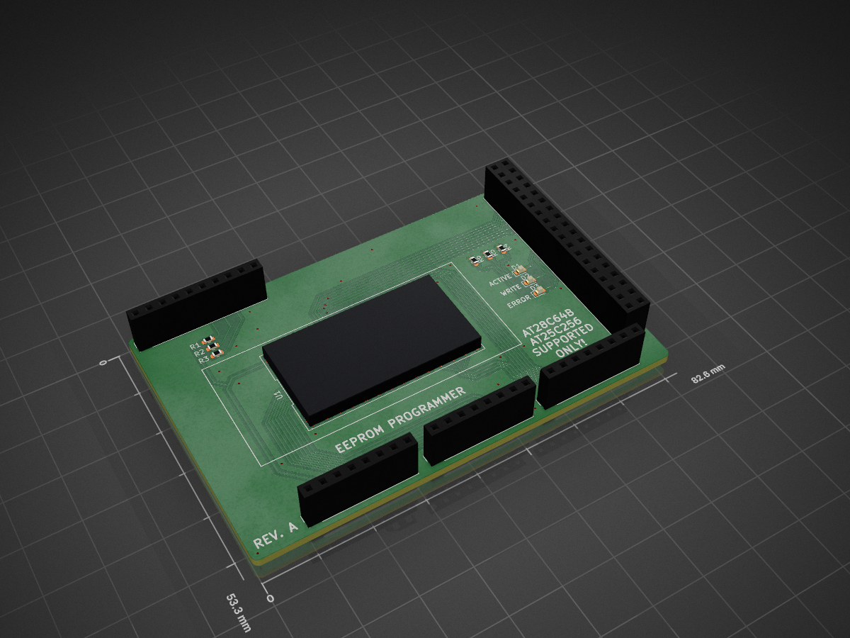
Socket shield is an open-source printed circuit board by ksmonkey123, from the ksmonkey123/eeprom-programmer repository on GitHub, published under the MIT licence. It is a 2-layer board of 82.6 × 53.3 mm with 15 parts on 66 nets, routed with 302 tracks and 33 vias.
Its parts include 6 resistors, 5 connectors, 3 diodes and 1 IC. It belongs with the interfaces and adapters boards of this library.
Arduino-based EEPROM programmer for the AT28C64B (8 KiB) and AT28C256 (32 KiB) EEPROMs.
The EEPROM programmer consists of 2 parts: A Programmer Device based consiting of an Arduino Mega 2560 with a daughter-board containing an IC socket for the EEPROM chips (DIP-28P6). This Programmer Device interacts with a Client Program on the PC.
The programmer supports enabling and disabling of the Software Data Protection (Write Lockout) mode on the EEPROM.
This feature can be used as a standalone command (<cmd> lock and <cmd> unlock), and in combination with other write
operations.
It is even possible to unlock an EEPROM, write to it, and lock it again in a single operation.
Since the programmer supports 2 different sizes of EEPROMs, the user would have to indicate what type is connected to the programmer for any given command. The Client Program is, however, capable of "guessing" the safe EEPROM size for most operations. In some cases this may lead to additional unnecessary write cycles on smaller chips (which we consider to be a negligible downside) and potentially increased operation durations.
The following pseudo-C shows the test routine to definitely determine the EEPROM size. This test can be performed both destructively and non-desctructively. In all cases the EEPROM must be unlocked beforehand.
bool isLargeChip(bool preserveData) {
  address adr = random(0x0000, 0x2000);
  byte data = read(adr);

  // if there's different data in the higher "blocks", it obviously is a large chip
  if (data != read(adr + 0x2000)) {
    return true;
  }

  // modify low byte, check if high byte changes too
  write(adr, ~data);
  //high byte unchanged means large chip
  bool result = (data == read(adr + 0x2000));

  if (preserveData) {
    write(adr, data);
  }
  return result;
}Unnecessary Write operations are avoided whenever possible. This means that the programmer will not write to a byte if the new value is the same as the old one. This reduces both write times and wear on the EEPROM.
The erase opration writes 0xFF to every byte of the EEPROM memory.
When an explicit size flag is set, the corresponding deletion logic is performed.
Otherwise, we perform a destructive size test before flashing the EEPROM.
The dump command reads the entire contents of the EEPROM.
If a size is specified, the output file has the matching size.
If no size is specified, the EEPROM is read as if it were a 32 KiB one.
After that the data is checked.
If all 4 8 KiB blocks match exactly, we assume to have read an 8 KiB EEPROM and write the output file with the
matching size.
If there are any differences in the blocks, we save the entire 32 KiB.
The flash command writes a binary file to the EEPROM.
In cases where no chip size is provided, we perform a size test before flashing the EEPROM. It is always possible to write a binary file to the EEPROM that is smaller than the capacity of the EEPROM. In that case, the memory locations not defined by the file remain unchanged.
It is never possible to write a file to an EEPROM that does not have enough capacity.
While the EEPROMs can be unlocked during write operations (erase / flash), a dedicated unlock command is also
provided.
Size information is not required for this operation.
While the EEPROMs can be locked during write operations (erase / flash), a dedicated lock command is also provided.
Size information is not required for this operation.
| Qty | Value | Footprint | References |
|---|---|---|---|
| 6 | R | Resistor_SMD:R_0603_1608Metric | R1, R2, R3, R4, R5, R6 |
| 3 | LED | LED_SMD:LED_0603_1608Metric | D1, D2, D3 |
| 2 | Analog | Connector_PinSocket_2.54mm:PinSocket_1x08_P2.54mm_Vertical | J3, J5 |
| 1 | Digital | Connector_PinSocket_2.54mm:PinSocket_2x18_P2.54mm_Vertical | J7 |
| 1 | PWM | Connector_PinSocket_2.54mm:PinSocket_1x10_P2.54mm_Vertical | J2 |
| 1 | Power | Connector_PinSocket_2.54mm:PinSocket_1x08_P2.54mm_Vertical | J1 |
| 1 | ~ | customs-fp:DIP-28_600_ELL | U1 |
It measures 82.6 × 53.3 mm and has 2 copper layers, 1.6 mm thick.
15 parts. The full list of its parts is on this page, with links to each part's symbol and footprint where PCBKit's library has them.
From the ksmonkey123/eeprom-programmer repository on GitHub, at the commit this page was made from: the board is pcbs/socket_shield/socket_shield.kicad_pcb and its schematic pcbs/socket_shield/socket_shield.kicad_sch. PCBKit opens the board in the browser, with nothing to install.
Its repository publishes it under the MIT licence: you may reuse it on that licence's terms (keep the author's notice, and for a copyleft licence share your changes alike).
google/mozc-devices
Circuit diagrams and firmware source code for Gboard DIY keyboards

hoglet67/RGBtoHDMI
Bare-metal Raspberry Pi project that provides pixel-perfect sampling of Retro Computer RGB/YUV video and conversion to HDMI

mntmn/amiga2000-gfxcard
MNT VA2000, an Open Source Amiga 2/3/4000 Graphics Card (Zorro II/III), written in Verilog

hackclub/OnBoard
💡 Join 1,000 teenagers and make your first PCB with a $100 grant!

kenp-io/not-for-airpods-repairs
The content of this repository is licensed under the WTFPL License. Please have a close look at the terms before using this material.

Luos-io/luos_engine
Open-source and real-time orchestrator for cyber-physical-systems, to easily design, test and deploy embedded applications and digital twins.

Chrismettal/EleLab_v2
Cheap DIY lab system for hobbyists and the tinkering folk
