
2 layers80 × 60 mm

 kryo-77/not-a-block
Note Block from Minecraft but in real life,
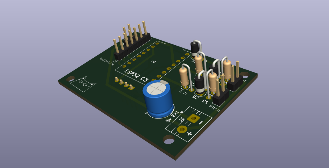
Not a block is an open-source printed circuit board by kryo-77, from the kryo-77/not-a-block repository on GitHub. It is a 2-layer board of 57.5 × 40 mm with 19 parts on 20 nets, routed with 84 tracks and 0 vias.
It is built around the BZX55C3V3. Its parts include 6 connectors, 4 resistors, 3 diodes, 1 capacitor and 1 IC. It belongs with the ESP32 and RISC-V boards of this library.
Note block from Minecraft but in real life.
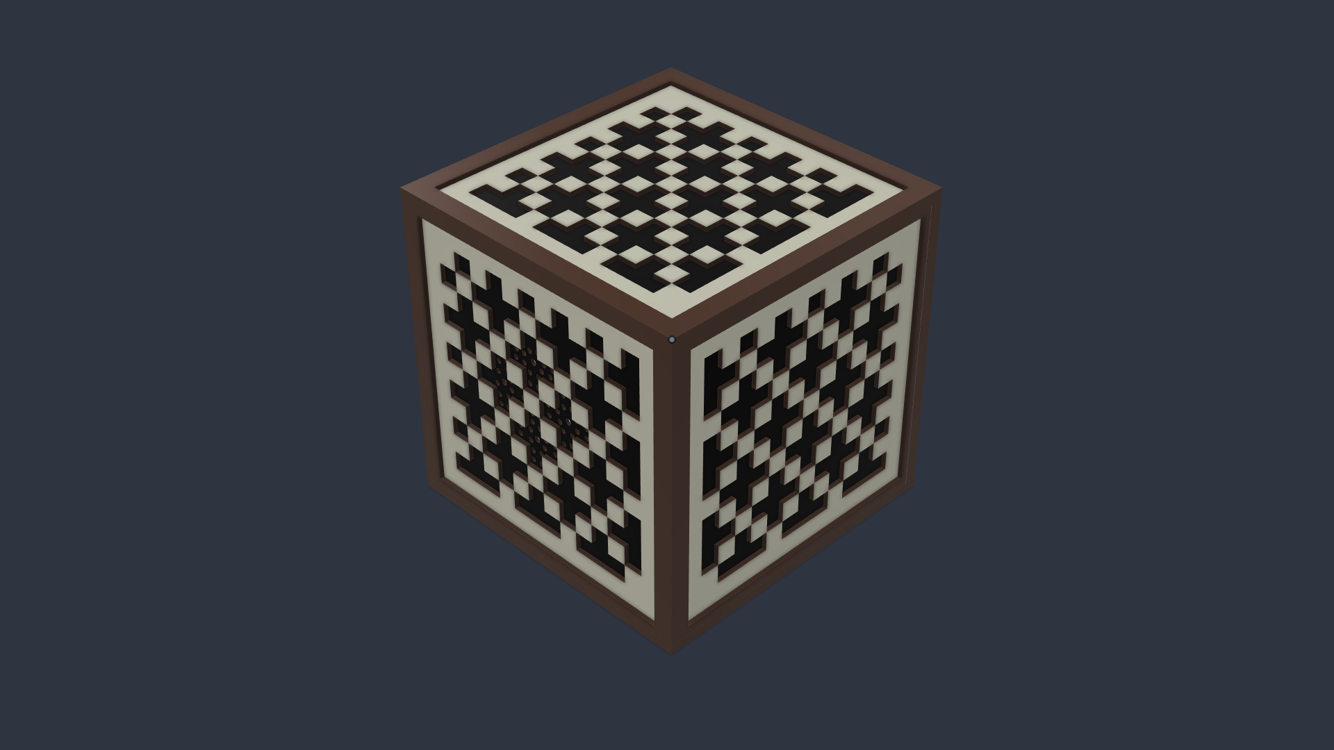
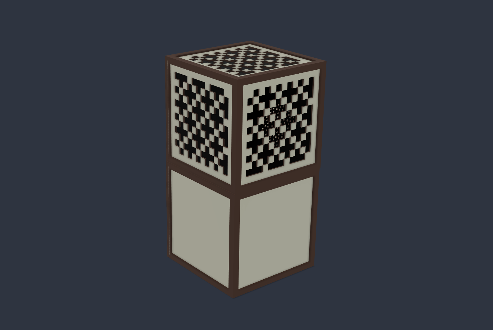
I made a note block from Minecraft which functions close enough to the actual game. You can tap the top face of the note block to play it and hit the back side of it to change the pitch (like right-clicking in Minecraft).
You can change the sound of the note block by placing it on different types of blocks as well. This is possible as there is an RFID card reader underneath the note block and a RFID tag on top of the instrument block (like stone, glass, sand, etc.)
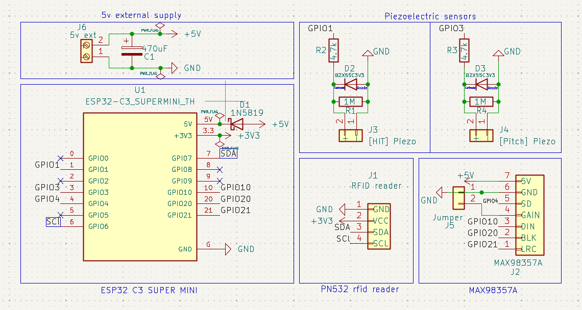
The note block contains an ESP-32-C3-SuperMini. It's the microcontroller which connects to different components. It also stores music files inside its flash memory. As the music files are under a second, we can store quite a lot of them inside the ESP32, so there is no need for a SD card module (which also saves pins). Sound is played by a MAX98357A I2S amp with a 4Ω 3W speaker (50mm diameter).
There are 2 piezoelectric sensors present inside the note block's top and back surface. When you hit the surface, the piezo sends voltage to the ESP32's data pin which tells it to play the sound.
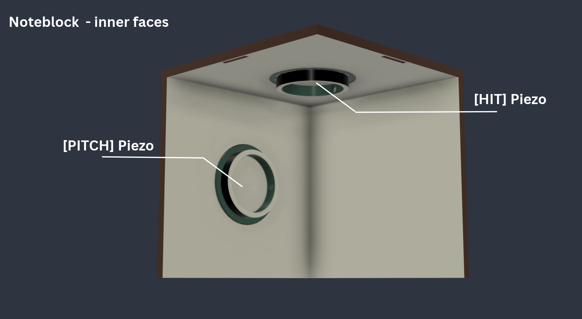
There are 16 different instrument sounds which the note block can play, which depend on the block below it. When the top surface is hit, it only tells ESP32 to play a single sound each time. When the back surface is hit, which is for changing the pitch of the instrument, each hit changes the sound to a different pitch. We don't need to have different audio inside the ESP32 for each pitch, as it can directly change on its own. Only the instrument sounds are needed to be stored.
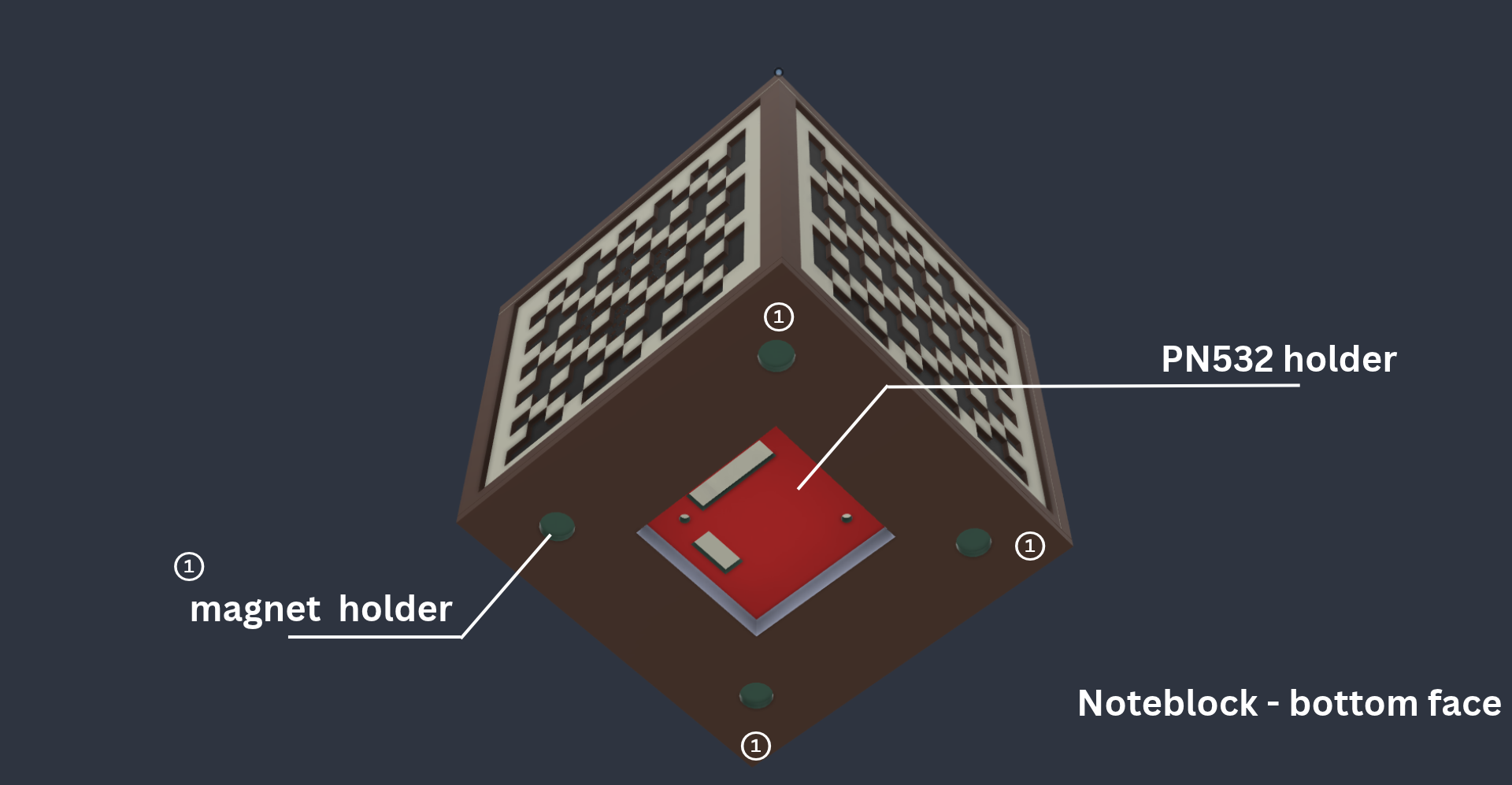
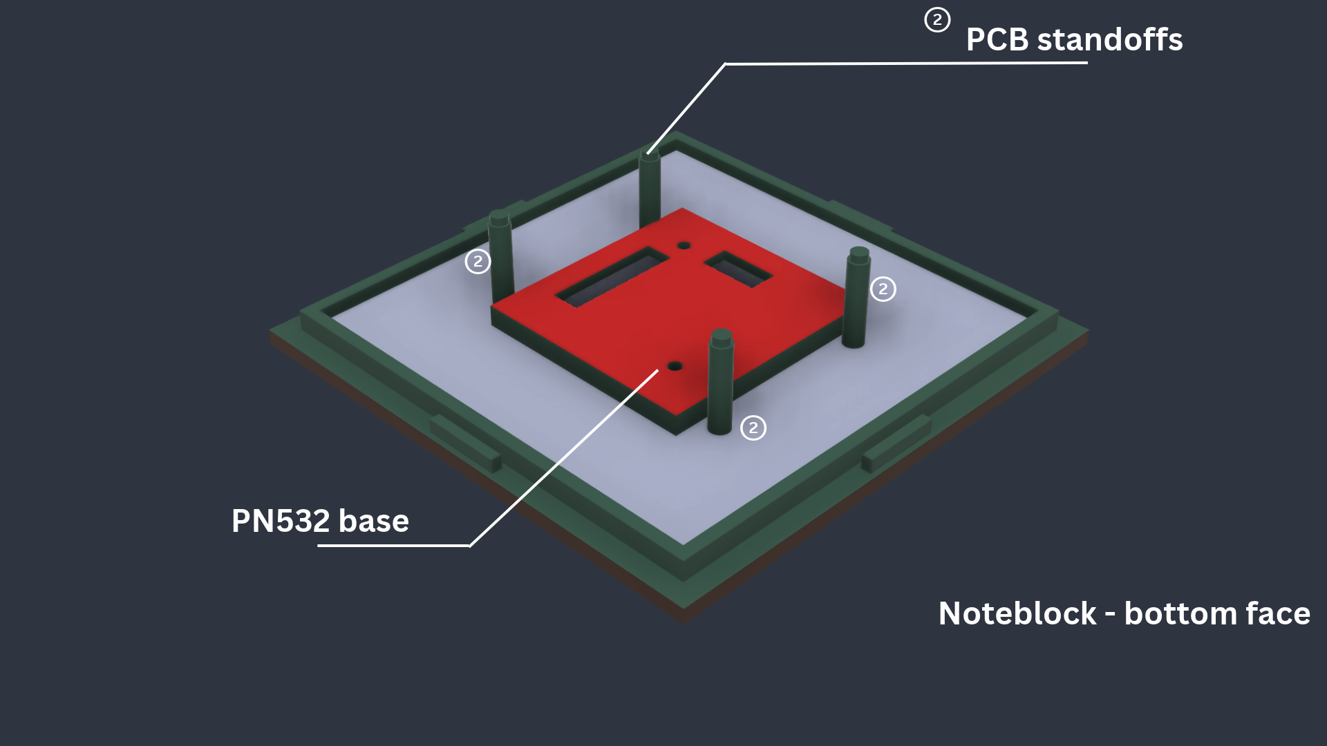
For detecting which block is present below the note block, a PN532 RFID card reader sits on the bottom surface, while a RFID tag sits on the top surface of the other blocks. The tag gets read every few seconds so that if the block changes, its sound changes as well without a lot of delay. 4 magnets are also present under the note block's surface as well as an instrument block's top surface, so that lining up the tags as well as the blocks is very easy. The magnets are also in different polarities (NN/SS) on the surfaces so you don't accidentally misplace back of the note block (where you hit to change pitch).
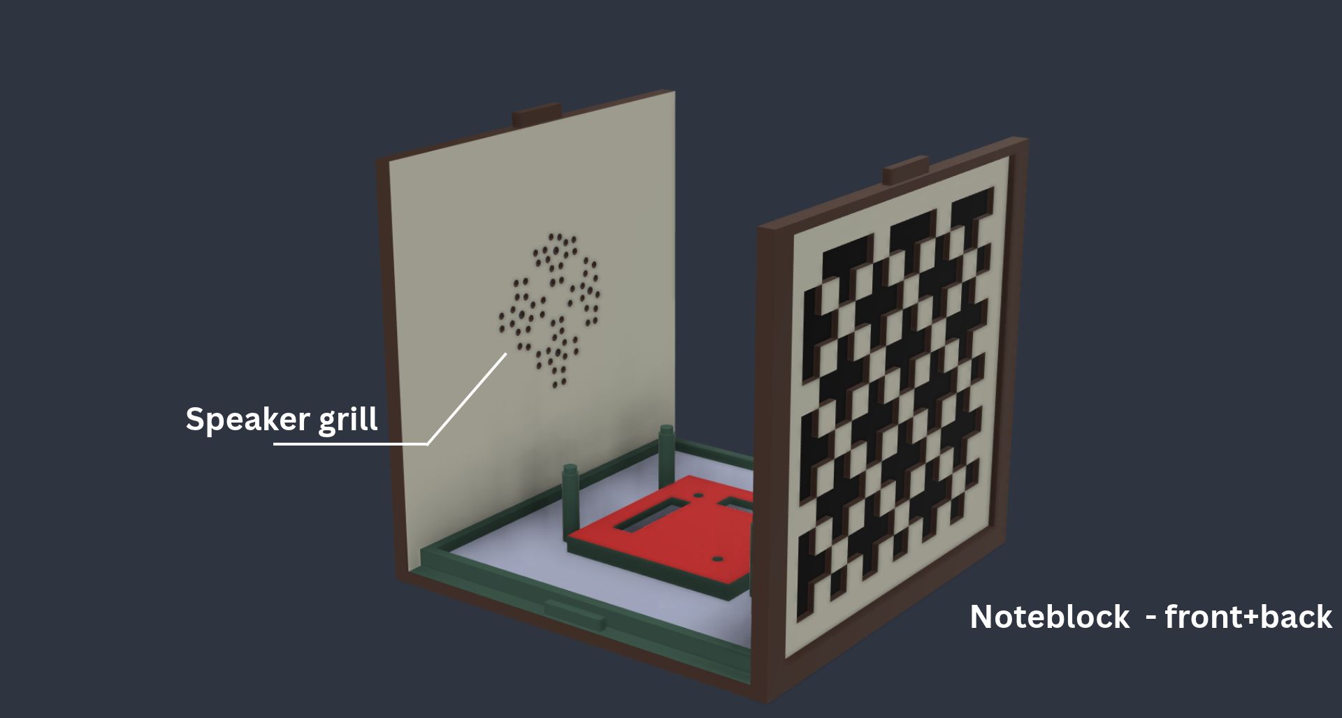
The front surface of the note block contains holes so that the speaker can output sound. I decided to only make holes in the black layer as it is thinner than the white one and would not show that many holes as well.
CAD folder contains .f3d (fusion) file & .stl for printing.PCB folder contains kicad files, export.zip has gerber files, 3d_model has .step file of PCB. It has a footprints_ext folder which contains footprint for ESP32-C3-SuperMini which I downloaded online.CODE folder contains basic test code (when RFID card gets detected, a beep is produced) which uses a XIAO s3, MFRC522 RFID reader and no piezo sensor. I only had these components with me so code are based on it instead of the BOM.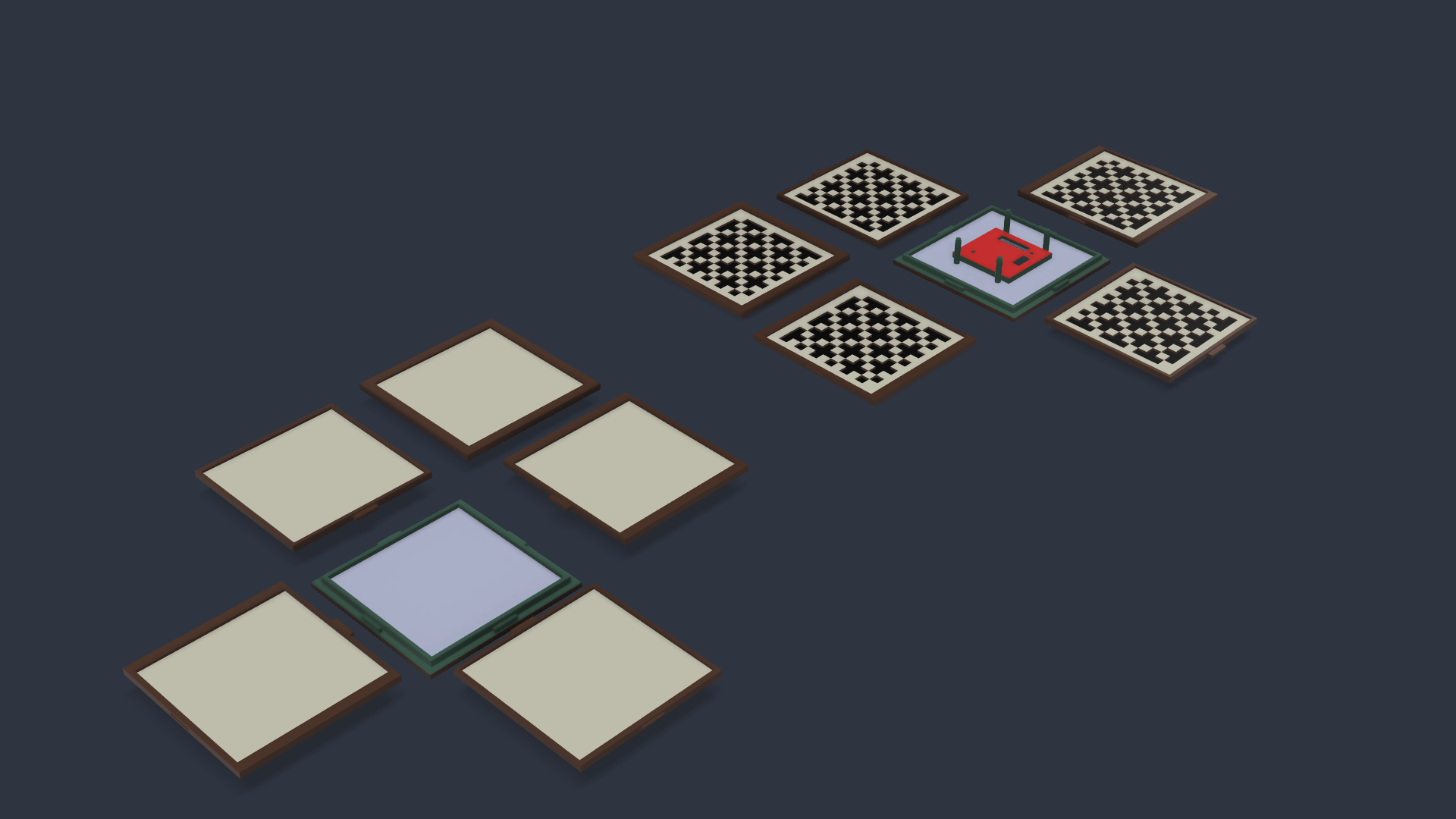
There are two types of block: Note block and Instrument block. Note block contains the electronics while the instrument block only contains a single RFID tag + 4 magnets on its top surface.
There are 6 parts per block. Final assembly should measure 10x10x10cm.
The faces are different sizes as all need to fit together to form the 10x10x10cm. It is pretty easy to assemble as same dimension face are opposites of each other.
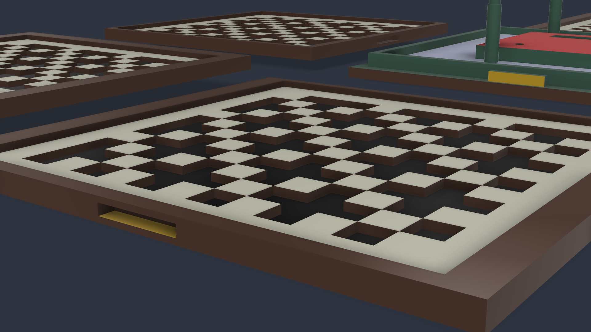
Each face has a rectangular hole on its bottom surface and a rectangle sticking out on its top surface.
The hole attaches to the base plate, while the rectangle goes in the top plate
Thats it for the assembly, just pushing the faces on to the base, no need for screws. Though the design might get changed depending on it actually works irl as I cant test the prints myself.
Screws aren't really needed other than mounting the pcb, that too is optional as I've made standoffs on the base plate.
| No | Component | Qty | Unit Price (USD) | Uses | Link |
|---|---|---|---|---|---|
| 1 | ESP32-C3 SuperMini | 1 | 2.72 | MCU | https://makerbazar.in/products/esp32-c3-supermini-iot-development-board |
| 2 | PN532 RFID/NFC V3 module | 1 | 2.83 | RFID reader | https://robocraze.com/products/nfc-near-field-communication-rf-id-v3-module |
| 3 | MAX98357A I2S amplifier | 1 | 2.04 | Sound amplifier | https://robu.in/product/smartelex-i2s-audio-breakout-max98357a/ |
| 4 | Speaker, 4 ohm 3W | 1 | 1.05 | Sound output | Local shop |
| 5 | 35mm piezo sensor | 2 | 0.23 | Hit and pitch sensing | https://robocraze.com/products/35mm-piezo-sensor |
| 6 | BZX55C3V3 zener diode | 2 | 0.02 | Piezo protection | https://robu.in/product/bzx55c3v3-1-2w-zener-diode-pack-of-40/ |
| 7 | 4.7k resistor | 2 | n/a | Piezo protection | |
| 8 | 470uF polarised capacitor | 1 | n/a | Power smoothing | |
| 9 | 1N5819 Schottky diode | 1 | 0.06 | Power protection (USB and battery connected together) | https://robu.in/product/1n5819-ap-mcc-40v-1a-600mv1a-do-41-schottky-diodes-rohs/ |
| 10 | 3d print | 1 | 14.55 | 3d print | (printing legion channel - slack) https://print.speedhawks.online/slice |
| 11 | PCB | 1 | 9.48 | PCB manufacturing | https://robu.in/product/online-pcb-manufacturing-service/ |
| Qty | Value | Footprint | References |
|---|---|---|---|
| 4 | , , , | ||
| 2 | 1M | Resistor_THT:R_Axial_DIN0207_L6.3mm_D2.5mm_P2.54mm_Vertical | R1, R4 |
| 2 | 4.7k | Resistor_THT:R_Axial_DIN0207_L6.3mm_D2.5mm_P2.54mm_Vertical | R2, R3 |
| 2 | BZX55C3V3 | Diode_THT:D_DO-41_SOD81_P2.54mm_Vertical_AnodeUp | D2, D3 |
| 1 | 1N5819 | Diode_THT:D_DO-41_SOD81_P2.54mm_Vertical_AnodeUp | D1 |
| 1 | 470uF | Capacitor_THT:CP_Radial_D8.0mm_P3.50mm | C1 |
| 1 | 5v ext | TerminalBlock:TerminalBlock_MaiXu_MX126-5.0-02P_1x02_P5.00mm | J6 |
| 1 | ESP32-C3_SUPERMINI_TH | MODULE_ESP32-C3_SUPERMINI_TH:MODULE_ESP32-C3_SUPERMINI_TH | U1 |
| 1 | Jumper | Connector_PinHeader_2.54mm:PinHeader_1x02_P2.54mm_Vertical | J5 |
| 1 | MAX98357A | Connector_PinHeader_2.54mm:PinHeader_1x07_P2.54mm_Vertical | J2 |
| 1 | RFID reader | Connector_PinHeader_2.54mm:PinHeader_1x04_P2.54mm_Vertical | J1 |
| 1 | [HIT] Piezo | Connector_PinHeader_2.54mm:PinHeader_1x02_P2.54mm_Vertical | J3 |
| 1 | [Pitch] Piezo | Connector_PinHeader_2.54mm:PinHeader_1x02_P2.54mm_Vertical | J4 |


hackclub/OnBoard
💡 Join 1,000 teenagers and make your first PCB with a $100 grant!

polpo/picogus
Emulation of ISA sound cards and CD-ROM on Raspberry Pi Pico (GUS, SB/Adlib, MPU-401, Tandy, CMS, Panasonic CD-ROM) with USB mouse/joystick support


nkitanov/iaq_board
IAQ Board is a DIY (Do-It-Yourself) device for measuring internal air quality


Ardumower/ardumower
Develop an open source robotic lawn mower (HW+SW reference platform)
It measures 57.5 × 40 mm and has 2 copper layers, 1.6 mm thick.
19 parts, built around the BZX55C3V3. The full list of its parts is on this page, with links to each part's symbol and footprint where PCBKit's library has them.
From the kryo-77/not-a-block repository on GitHub, at the commit this page was made from: the board is PCB/notablock.kicad_pcb and its schematic PCB/notablock.kicad_sch. PCBKit opens the board in the browser, with nothing to install.
Its repository states no licence, so its author keeps all rights: ask kryo-77 before reusing the design.