2 layers116.8 × 30 mm
Type d
google/mozc-devices
Circuit diagrams and firmware source code for Gboard DIY keyboards
14 parts3kApache-2.0

 konspyre/fade2
A USB volume controller
Fade is an open-source printed circuit board by konspyre, from the konspyre/fade repository on GitHub. It is a 2-layer board of 34.7 × 16.8 mm with 14 parts on 11 nets, routed with 119 tracks and 4 vias.
Its parts include 5 resistors, 3 diodes, 3 connectors, 2 capacitors and 1 IC. It belongs with the AVR (ATmega, ATtiny) boards of this library.
This is a generalized development board for V-USB, using the ATTiny85 without a crystal.
The board files are free for re-use, modification, and manufacture without restriction.
The repository here contains KiCAD sources (schematic/board files), basic V-USB code that implements a key-based HID media controller (with modifications for this board) and a Bill of Materials listing.
Note: The VID/PID need to be properly defined before using this board in production. This should be your own VID/PID, or from a source such as http://pid.codes.
| Pin on ATTiny | Goes to | Connected to ISP as |
|---|---|---|
| PB0 | Pin 2 on connector | MOSI |
| PB3 | Pin 3 on connector | Not Connected |
| PB4 | Pin 4 on connector | Not Connected |
| Quantity | Placement | Description | Digikey Part Number | Notes |
|---|---|---|---|---|
| 1 | Center, with corner dot aligned to silkscreened dot | ATTiny85 (PDIP) | ATTINY85-20PU-ND | ATTiny in PDIP format |
| 1 | 2.2K | 2.2K ohm resistor | 1276-5070-1-ND | Pull-up resistor for D- (0603 imperial) |
| 1 | 4.7K | 4.7k ohm resistor | P4.7KGCT-ND | Pull-up resistor for AVR RESET line (0603 imperial) |
| 1 | C1 | 10uF 16V 20% X6S capacitor | 490-10499-1-ND | Bypass at USB input (0805 imperial) |
| 1 | C2 | 0.1uF capacitor | 490-1532-1-ND | Just buy a bunch. Singles are expensive! (0603 imperial) |
| 1 | USB box at board edge (4 pads with plated through-holes) | USB connector | WM17116CT-ND | Mini USB-B |
| 2 | 68R | 68 ohm resistor | 311-68GRCT-ND | USB data terminators (0603 imperial) |
| 2 | D1+D2 with striped side opposite board markings | 3.6V Zener diode | BZT52C3V6-E3-08-ND | SOD123 format |
| Quantity | Placement | Description | Digikey Part Number | Notes |
|---|---|---|---|---|
| 1 | ATTiny footprint (aligned with the U silk) | 8 pin DIP socket | A120347-ND | The older socket used in prototypes was P/N 390261-2 and was discontinued |
| 1 | 330R | 330 ohm resistor | 1276-5050-1-ND | Current limiting resistor for PWR LED |
| 1 | Next to 330R (+ - silk) | Power LED | 475-2512-1-ND | Red LED 0603 imperial |
| 1 | +5V / GND silk-screened box | Right angle 1x5 female header | S5480-ND | For connecting to carrier boards (female header) |
| 1 | +5V / GND silkscreened box | Right angle 1x5 male header | S1121E-05-ND | For connecting to carrier boards (male header) |
| 1 | 2x3 header | 6 pin AVR ISP header | 3M9459-ND | For flashing the ATTiny85 |
Ensure that you have all the avr tools necessary to compile the firmware. On Debian/Ubuntu based systems the dependencies are:
sudo apt-get install -y build-essential gcc-avr gdb-avr binutils-avr avr-libc avrdudeIn the firmware directory (depending on how your system permissions are setup pre-pending sudo may be necessary):
cd firmware
make hex
make program
make fuseThese must be programmed, otherwise your board will not enumerate with the host.
avrdude -c buspirate -p attiny85 -P /dev/ttyUSB0
 -U hfuse:w:0xdd:m -U lfuse:w:0xe1:m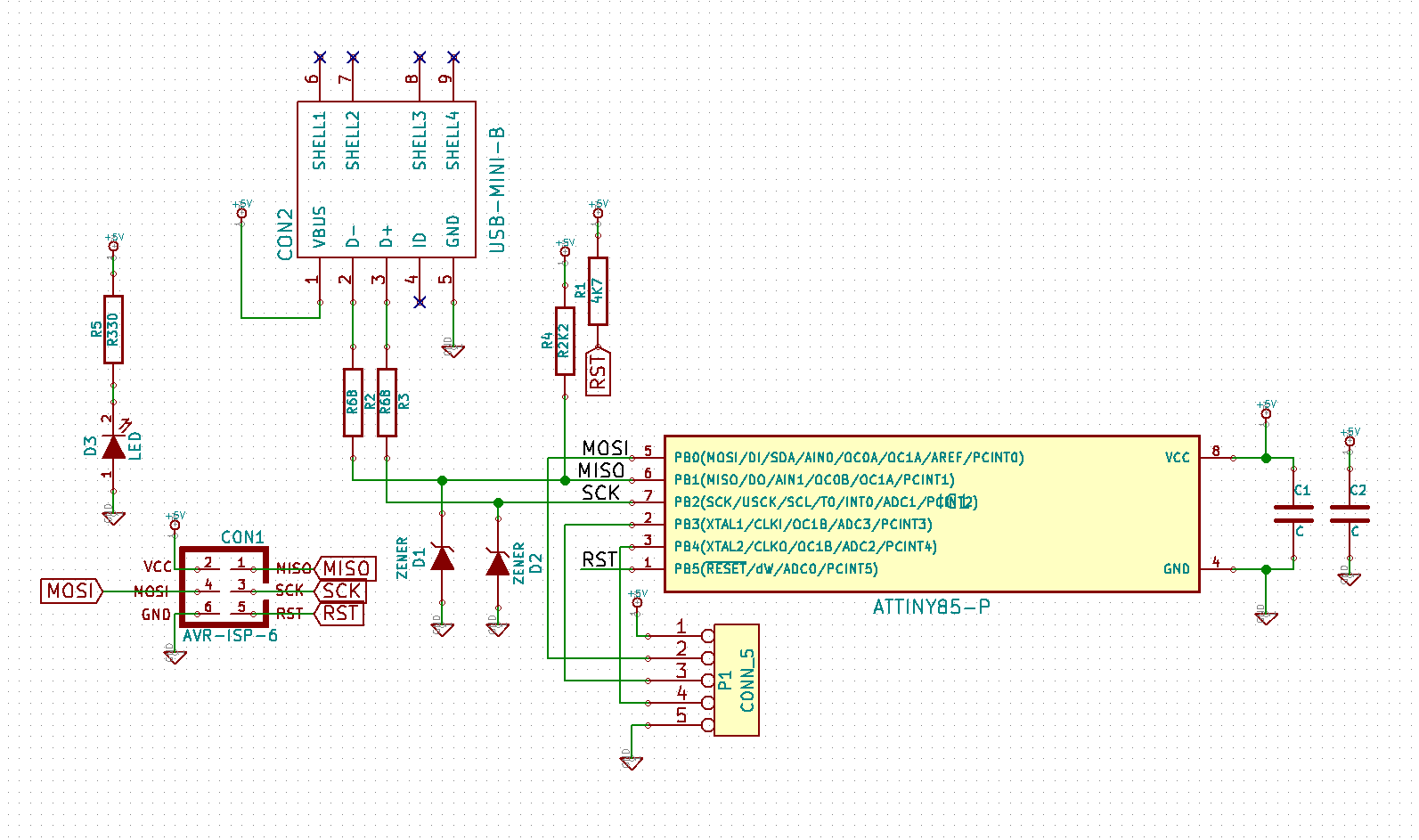
Board files, schematic and PCB are CC0 1.0 Universal.
V-USB firmware and accompanying source code is GPL 2.0 licensed.
For more information and full license text, see the LICENSE.md file in this repository.
| Qty | Value | Footprint | References |
|---|---|---|---|
| 2 | R68 | SM0603 | R2, R3 |
| 2 | ZENER | Cherry:BZT52C3V6-E3-08 | D1, D2 |
| 1 | 4K7 | SM0603 | R1 |
| 1 | ATTINY85-P | Power_Integrations:PDIP-8 | IC1 |
| 1 | AVR-ISP-6 | AVR-ISP-6 | CON1 |
| 1 | C | Capacitors_SMD:c_0603 | C1 |
| 1 | C | Capacitors_SMD:c_0805 | C2 |
| 1 | CONN_5 | Pin_Headers:Pin_Header_Straight_1x05 | P1 |
| 1 | LED | LEDs:LED-0603 | D3 |
| 1 | R2K2 | SMD_Packages:SM0603 | R4 |
| 1 | R330 | SMD_Packages:SM0603 | R5 |
| 1 | USB-MINI-B | Cherry:USB_MINI_B_SMT | CON2 |
google/mozc-devices
Circuit diagrams and firmware source code for Gboard DIY keyboards


hackclub/OnBoard
💡 Join 1,000 teenagers and make your first PCB with a $100 grant!


Twotoz/C5VRX
Ultra-minimal, zero-CPU 5.8 GHz analog FPV video receiver using ESP32-C5 Wi-Fi 6 PHY MODEM_DIAG, BitScrambler WBFM demodulation & resistor DAC CVBS


It measures 34.7 × 16.8 mm and has 2 copper layers, 1.6 mm thick.
14 parts. The full list of its parts is on this page, with links to each part's symbol and footprint where PCBKit's library has them.
From the konspyre/fade repository on GitHub, at the commit this page was made from: the board is pcb/fade.kicad_pcb. PCBKit opens the board in the browser, with nothing to install.
Its repository states no licence, so its author keeps all rights: ask konspyre before reusing the design.