2 layers34.5 × 24 mm

 koko69420/UV-Curing-Box
UV PCB resin curing box controller using WCH CH32V003 RISC-V MCU, 4x4 keypad, TM1637 display, and KiCad PCB
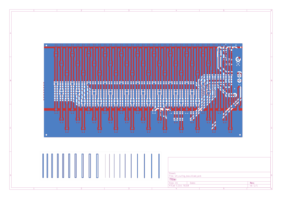
UV Curing Box is an open-source printed circuit board by koko69420, from the koko69420/UV-Curing-Box repository on GitHub. It is a 2-layer board of 213.7 × 144.8 mm with 151 parts on 120 nets, routed with 282 tracks and 3 vias.
It is built around the CH32V003A4M6, AMS1117-5.0 and AO3400A, with the SS54 among its other parts. Its parts include 100 diodes, 36 resistors, 5 connectors, 4 capacitors and 2 ICs. It belongs with the lEDs and displays and keyboards and input boards and the RISC-V boards of this library.


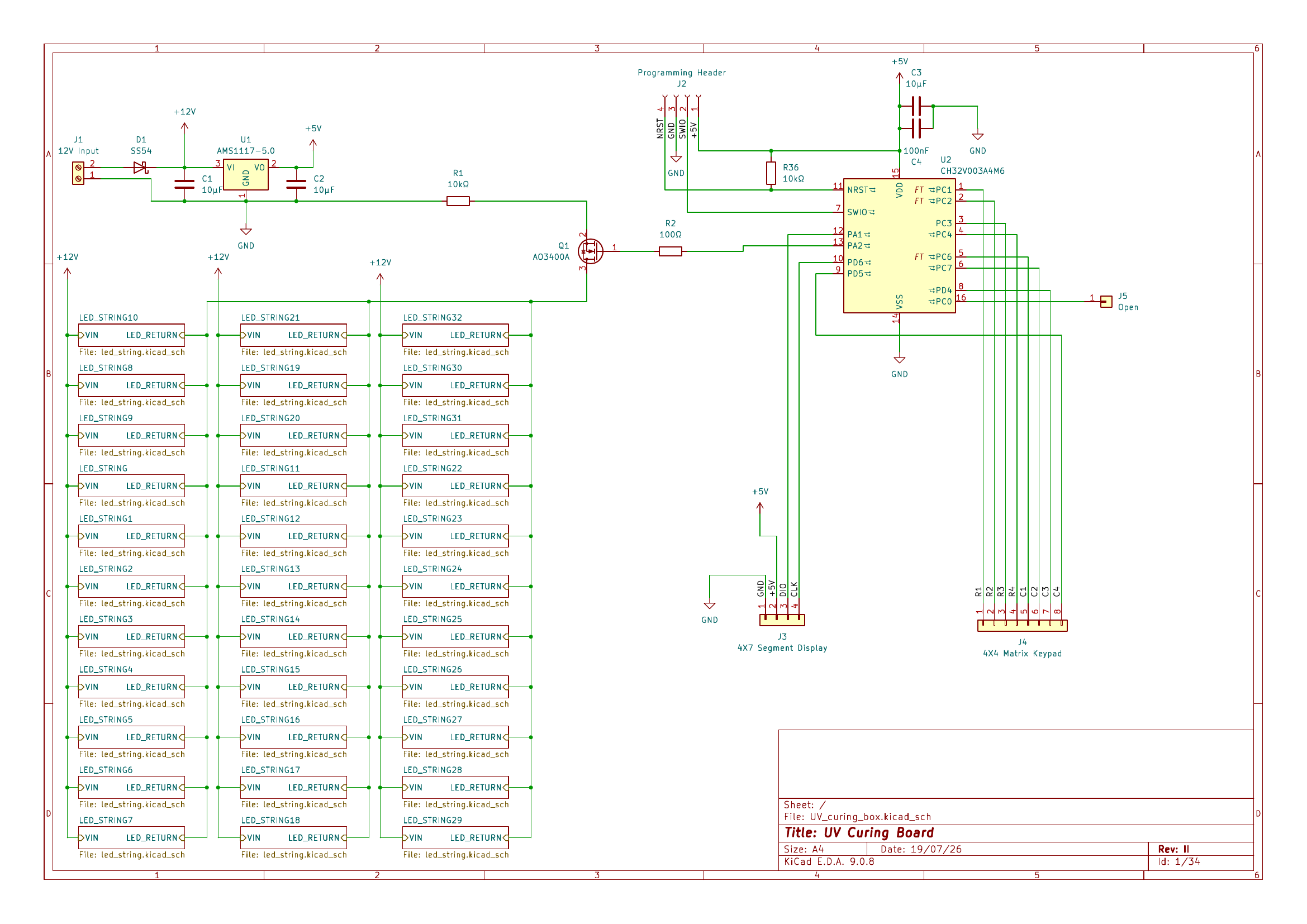
A dedicated, safety-interlocked UV exposure and resin curing chamber controller powered by the ultra-low-cost WCH CH32V003 RISC-V microcontroller, featuring a 4x4 matrix keypad, a 4-digit TM1637 7-segment display, software PWM brightness control, and custom KiCad hardware.
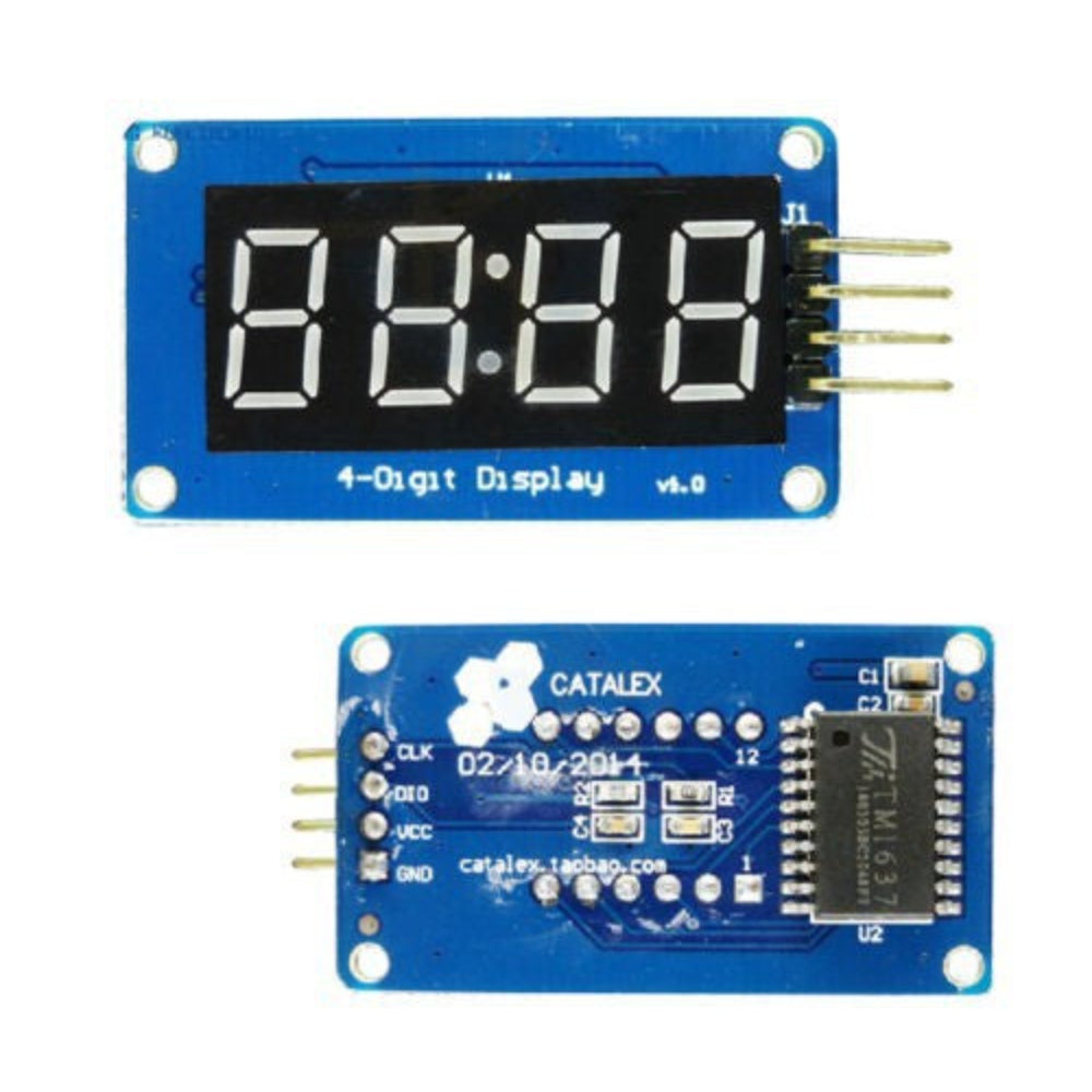
ch32v003fun HAL).RUNNING state.BOOT, IDLE, READY, PAUSED, or FINISHED instantly and continuously force the gate LOW.# button adds +5 seconds, clamped to 8:00).b 0 to b100).Below is the operational controller prototype executing a countdown exposure on the TM1637 4-digit display:
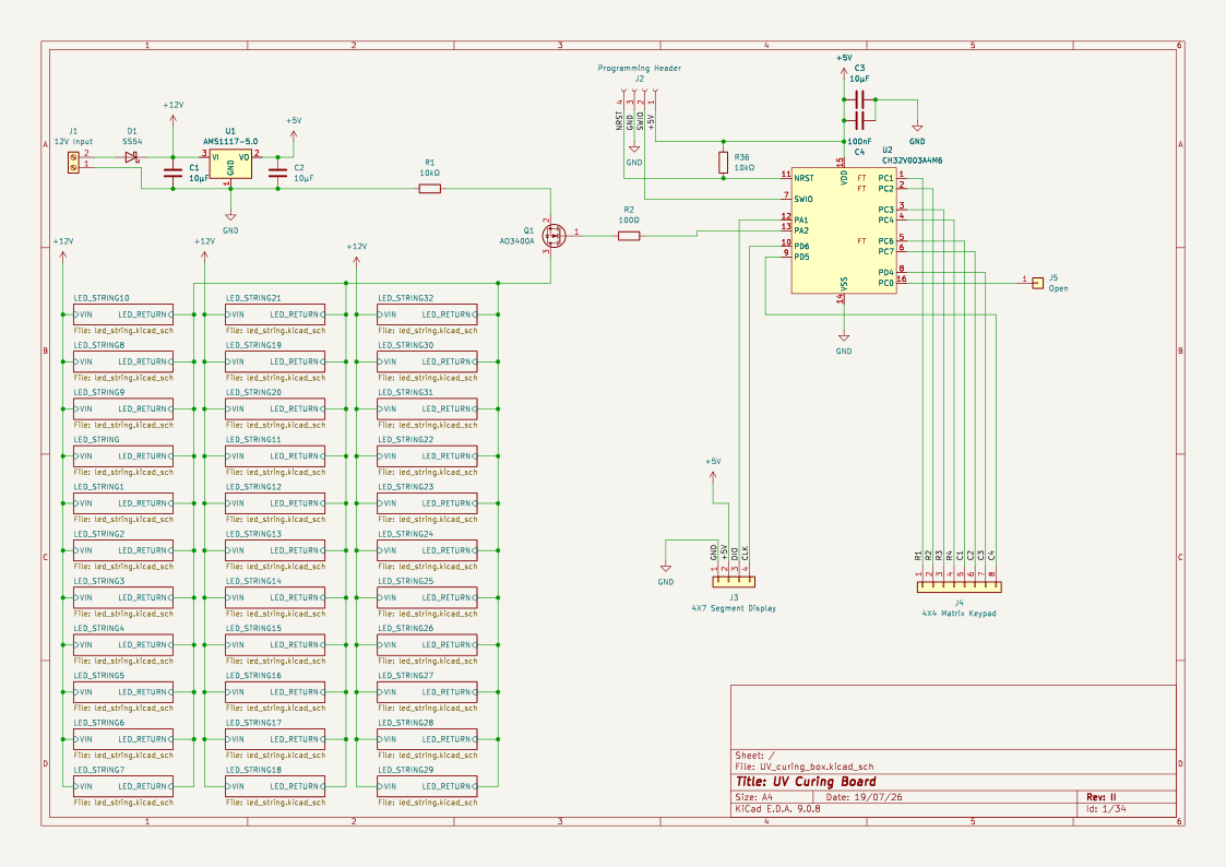
| Complete Board Layout | Top Copper Layer (F_Cu) | Bottom Copper Layer (B_Cu) |
|---|---|---|
 |  | 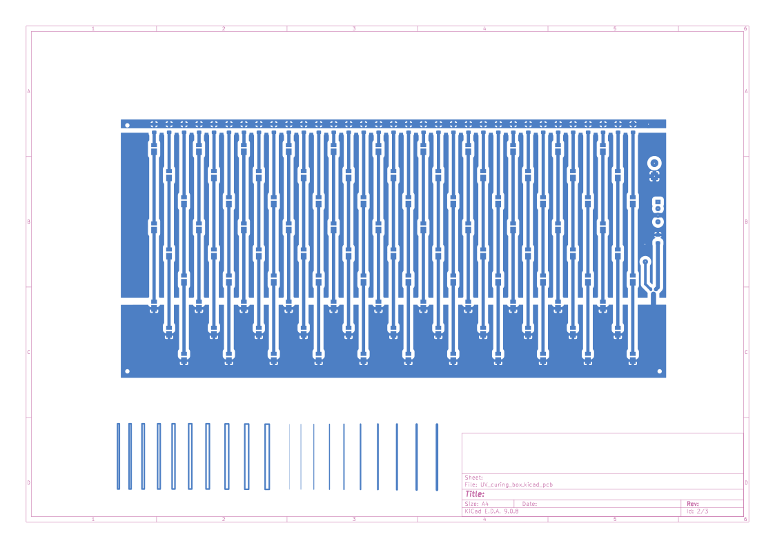 |
| Function | Pin Name | Direction | Description |
|---|---|---|---|
| Keypad Row 1 | C1 | Output | Matrix row scan line 1 |
| Keypad Row 2 | C2 | Output | Matrix row scan line 2 |
| Keypad Row 3 | C3 | Output | Matrix row scan line 3 |
| Keypad Row 4 | C4 | Output | Matrix row scan line 4 |
| Keypad Col 1 | C6 | Input (Pullup) | Matrix column sense line 1 |
| Keypad Col 2 | C7 | Input (Pullup) | Matrix column sense line 2 |
| Keypad Col 3 | D4 | Input (Pullup) | Matrix column sense line 3 |
| Keypad Col 4 | D5 | Input (Pullup) | Matrix column sense line 4 |
| TM1637 CLK | D6 | Output | Display serial clock |
| TM1637 DIO | A1 | Bidirectional | Display serial data line |
| UV MOSFET Gate | A2 | Output | Low-side power gate driver (PWM) |
stateDiagram-v2
    [*] --> BOOT
    BOOT --> IDLE: Initialization Complete
    IDLE --> READY: Digit Entry or Preset (A-D)
    READY --> RUNNING: Press '#' (Start)
    RUNNING --> PAUSED: Press '*' (Pause)
    PAUSED --> RUNNING: Press '#' (Resume)
    PAUSED --> IDLE: Press '*' (Reset to Zero)
    RUNNING --> FINISHED: Time Reaches 0:00 (Timer) or 8:00 (Stopwatch)
FINISHED --> IDLE: 5s Auto-timeout or Any KeyUV-Curing-Box/
├── Programs/ # PlatformIO firmware project
│ ├── platformio.ini # CH32V003 target configuration
│ └── src/
│ └── main.cpp # Complete non-blocking state machine & firmware
├── Schematic.pdf # Schematic diagram export
├── UV_curing_box.kicad_sch # KiCad schematic
├── UV_curing_box.kicad_pcb # KiCad PCB board layout
├── MCU_WCH_CH32V003xxx6.kicad_sym # Custom CH32V003 symbol library
├── led_string.kicad_sch # UV LED array layout
├── UV_curing_box.svg # Scalable vector graphics board plot
├── .gitignore # Git ignore rules
└── README.md # Project documentationcd Programs
pio runpio run --target uploadOpen hardware and embedded firmware. All rights reserved by the author.
| Qty | Value | Footprint | References |
|---|---|---|---|
| 99 | LED | LED_SMD:LED_PLCC_2835_Handsoldering | D2, D10, D11, D12, D13, D14, D15, D16, D17, D18, D19, D20, D21, D22, D23, D100 +83 |
| 33 | 47Ω | Resistor_SMD:R_1206_3216Metric_Pad1.30x1.75mm_HandSolder | R10, R11, R12, R13, R14, R15, R16, R17, R18, R19, R20, R21, R22, R23, R24, R25 +17 |
| 3 | 10µF | Capacitor_SMD:C_1206_3216Metric_Pad1.33x1.80mm_HandSolder | C1, C2, C3 |
| 2 | , | ||
| 2 | 10kΩ | Resistor_SMD:R_1206_3216Metric_Pad1.30x1.75mm_HandSolder | R1, R36 |
| 1 | 100nF | Capacitor_SMD:C_1206_3216Metric_Pad1.33x1.80mm_HandSolder | C4 |
| 1 | 100Ω | Resistor_SMD:R_1206_3216Metric_Pad1.30x1.75mm_HandSolder | R2 |
| 1 | 12V Input | TerminalBlock:TerminalBlock_MaiXu_MX126-5.0-02P_1x02_P5.00mm | J1 |
| 1 | 4X4 Matrix Keypad | connector-smd:smd_conn_1x08_2.54 | J4 |
| 1 | 4X7 Segment Display | connector-smd:smd_conn_1x04_2.54 | J3 |
| 1 | AMS1117-5.0 | Package_TO_SOT_SMD:SOT-223-3_TabPin2 | U1 |
| 1 | AO3400A | Package_TO_SOT_SMD:SOT-23 | Q1 |
| 1 | CH32V003A4M6 | Package_SO:SO-16_3.9x9.9mm_P1.27mm | U2 |
| 1 | Open | Connector_Wire:SolderWirePad_1x01_SMD_1.5x3mm | J5 |
| 1 | Programming Header | Connector_PinSocket_2.54mm:PinSocket_1x04_P2.54mm_Vertical | J2 |
| 1 | SS54 | Diode_SMD:D_SMA_Handsoldering | D1 |
The 150 most common of 151 parts.


mithro/rpi-camera-led
Interposer for the Raspberry Pi camera flex cable: passes the 15-way CSI bus straight through and adds I2C-controlled camera GPIO, PWM illumination LEDs and an ambient light sensor, driven by a CH32V003.

BogdanTheGeek/CCCCPPPS
Cheap Crappy Constant Current Portable Programmable Power Supply

RSXLX/sunny-the-growing-sunflower-lamp
SUNNY — The Growing Sunflower Lamp | A personal lamp with customizable exteriors, traceable fabrication, and a local creative workspace.


tvlad1234/osillyscope
Low cost, low part count CH32V003-based oscilloscope

mverdon/ch32v003a4m6-breakout
Breakout board for prototyping with the CH32V003 MCU
It measures 213.7 × 144.8 mm and has 2 copper layers, 1.6 mm thick.
151 parts, built around the CH32V003A4M6, AMS1117-5.0, AO3400A and SS54. The full list of its parts is on this page, with links to each part's symbol and footprint where PCBKit's library has them.
From the koko69420/UV-Curing-Box repository on GitHub, at the commit this page was made from: the board is UV_curing_box.kicad_pcb and its schematic UV_curing_box.kicad_sch. PCBKit opens the board in the browser, with nothing to install.
Its repository states no licence, so its author keeps all rights: ask koko69420 before reusing the design.