2 layers
Nrf bga
github-linguist/linguist
Language Savant. If your repository's language is being reported incorrectly, send us a pull request!
12 parts14kMIT

 knulpi/pi-1wire-multi-shield1
Multi-Input 1-wire shield for Raspberry Pi's. Connect up to six 1-wire sensor busses to a Raspberry Pi. This is useful if you have long sensor lines or want to connect many sensors.
Pi-1w shield is an open-source printed circuit board by knulpi, from the knulpi/pi-1wire-multi-shield repository on GitHub, published under the MIT licence. It is a 2-layer board of 31.8 × 76.2 mm with 12 parts on 40 nets, routed with 55 tracks and 0 vias.
Its parts include 6 resistors, 4 connectors and 2 capacitors. It belongs with the sensors and measurement boards of this library.
Use up to six 1-wire bus lines to connect multiple sensors on long lines.
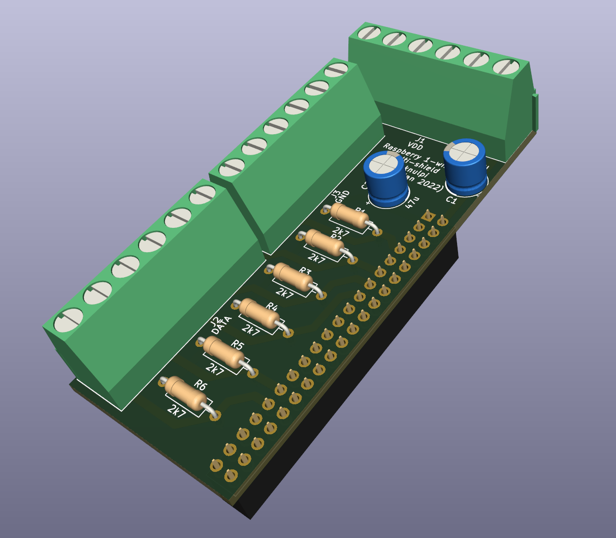
This is a project providing a circuit and PCB design for a Raspberry Pi shield. The board can connect up to six 1-wire buses, enabling to connect up to around 60 sensors, such as the DS18B20. Each data pin of the terminals is wired to one specific GPIO. The board can easily be plugged onto a Raspberry Pi.
Connecting 1-wire sensors with long lines is error-prone and will not work with many sensors. You may get random disappearing sensors or bad value readings. Splitting problematic sensor lines into own buses greatly reduces these inabilities.
The circuit is quite simple. It basically connects
Since the Raspberry's data pins operate at 3V3, the pull-up resistors for the data lines are using the 3V3 net of the Raspberry. The pull-ups are lower than the default recommended value (4k7). This should stabilize long bus lines.
Each power net has a 47uF capacitor for stabilization.

The PCB follows the schematic. The pin-header is mounted on the bottom side of the board (see images). This enables the board to be connected directly with the Raspberry pin headers.
Each screw terminal is connected to one net. There is one for GND, one for VDD and one for DATA. Be aware that you might reduce more insulation of your cables to reach all terminals.

The gerber files can be used to directly order the board, e.g. via Aisler.
The following parts are needed:
⚠ Your kernel must not be too old, so that it supports multiple 1-wire enabled GPIOs
To set up your Pi, enable each GPIO used for 1-wire protocol in your /boot/config.txt.
Every GPIO we connected will have its own line.
If you are unsure what to do, follow other tutorials in the web that describe the procedure in detail,
like this tutorial.
In the end, your /boot/config.txt file should contain these lines:
dtoverlay=w1-gpio,gpiopin=4
dtoverlay=w1-gpio,gpiopin=5
dtoverlay=w1-gpio,gpiopin=6
dtoverlay=w1-gpio,gpiopin=17
dtoverlay=w1-gpio,gpiopin=22
dtoverlay=w1-gpio,gpiopin=27
Restart and your sensors will appear in /sys/bus/w1/devices.
Feel free to open Pull Requests or just create issues if you feel that something is missing or can be improved.
| Qty | Value | Footprint | References |
|---|---|---|---|
| 6 | 2k7 | Resistor_THT:R_Axial_DIN0207_L6.3mm_D2.5mm_P10.16mm_Horizontal | R1, R2, R3, R4, R5, R6 |
| 2 | 47u | Capacitor_THT:CP_Radial_D6.3mm_P2.50mm | C1, C2 |
| 1 | DATA | TerminalBlock_Phoenix:TerminalBlock_Phoenix_MKDS-1,5-6-5.08_1x06_P5.08mm_Horizontal | J2 |
| 1 | GND | TerminalBlock_Phoenix:TerminalBlock_Phoenix_MKDS-1,5-6-5.08_1x06_P5.08mm_Horizontal | J3 |
| 1 | Raspberry_Pi_2_3 | Connector_PinSocket_2.54mm:PinSocket_2x20_P2.54mm_Vertical | J4 |
| 1 | VDD | TerminalBlock_Phoenix:TerminalBlock_Phoenix_MKDS-1,5-6-5.08_1x06_P5.08mm_Horizontal | J1 |
It measures 31.8 × 76.2 mm and has 2 copper layers, 1.6 mm thick.
12 parts. The full list of its parts is on this page, with links to each part's symbol and footprint where PCBKit's library has them.
From the knulpi/pi-1wire-multi-shield repository on GitHub, at the commit this page was made from: the board is kikad/pi-1w-shield.kicad_pcb and its schematic kikad/pi-1w-shield.kicad_sch. PCBKit opens the board in the browser, with nothing to install.
Its repository publishes it under the MIT licence: you may reuse it on that licence's terms (keep the author's notice, and for a copyleft licence share your changes alike).
github-linguist/linguist
Language Savant. If your repository's language is being reported incorrectly, send us a pull request!


google/mozc-devices
Circuit diagrams and firmware source code for Gboard DIY keyboards


hackclub/OnBoard
💡 Join 1,000 teenagers and make your first PCB with a $100 grant!

VoronDesign/Voron-Tap
Tap is a nozzle-based z-probe for the V2 and Trident printer designs. The entire toolhead moves to trigger an optical switch. Tap offers many advantages:

stacksmashing/pico-tpmsniffer
A simple, very experimental TPM sniffer for LPC bus