4 layers45.9 × 16.1 mm
LoRa
LorenzoCucchi/ELRS-SX1281
2.4 GHz LoRa board featuring the SX1281 and the SKY65383-11 frontend
36 parts1MIT

 klownfish/brage_telemetry
A CAN connected 1W 2.4GHz telemetry modem
1280 modem is an open-source printed circuit board by klownfish, from the klownfish/brage_telemetry repository on GitHub. It is a 4-layer board of 38 × 53 mm with 96 parts on 77 nets, routed with 764 tracks and 134 vias.
It is built around the SKY65383-11, SX1281IMLTRT and TCAN334GDCN, with the DEA202450BT-1213C1, USBLC6-2SC6 and SZNUP2105L among its other parts. Its parts include 35 capacitors, 21 resistors, 7 ICs, 7 diodes and 5 connectors. It belongs with the STM32 boards of this library.


Brage is a 1W 2.4GHz Telemetry modem that can listen and transmit from a CAN-bus. The name comes from the norse god of poetry, Brage, who will tell the tales of the rocket.
| front | back |
|---|---|
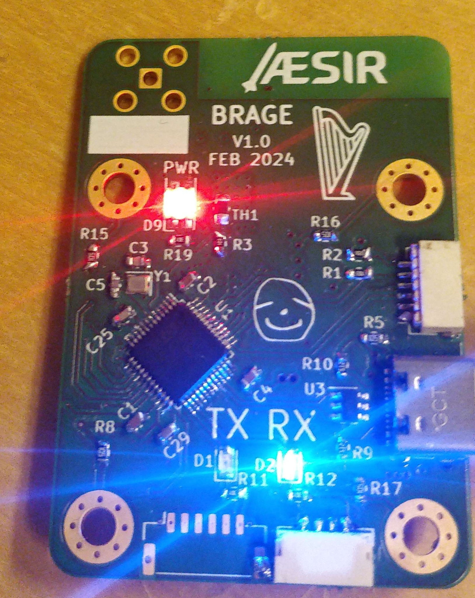 | 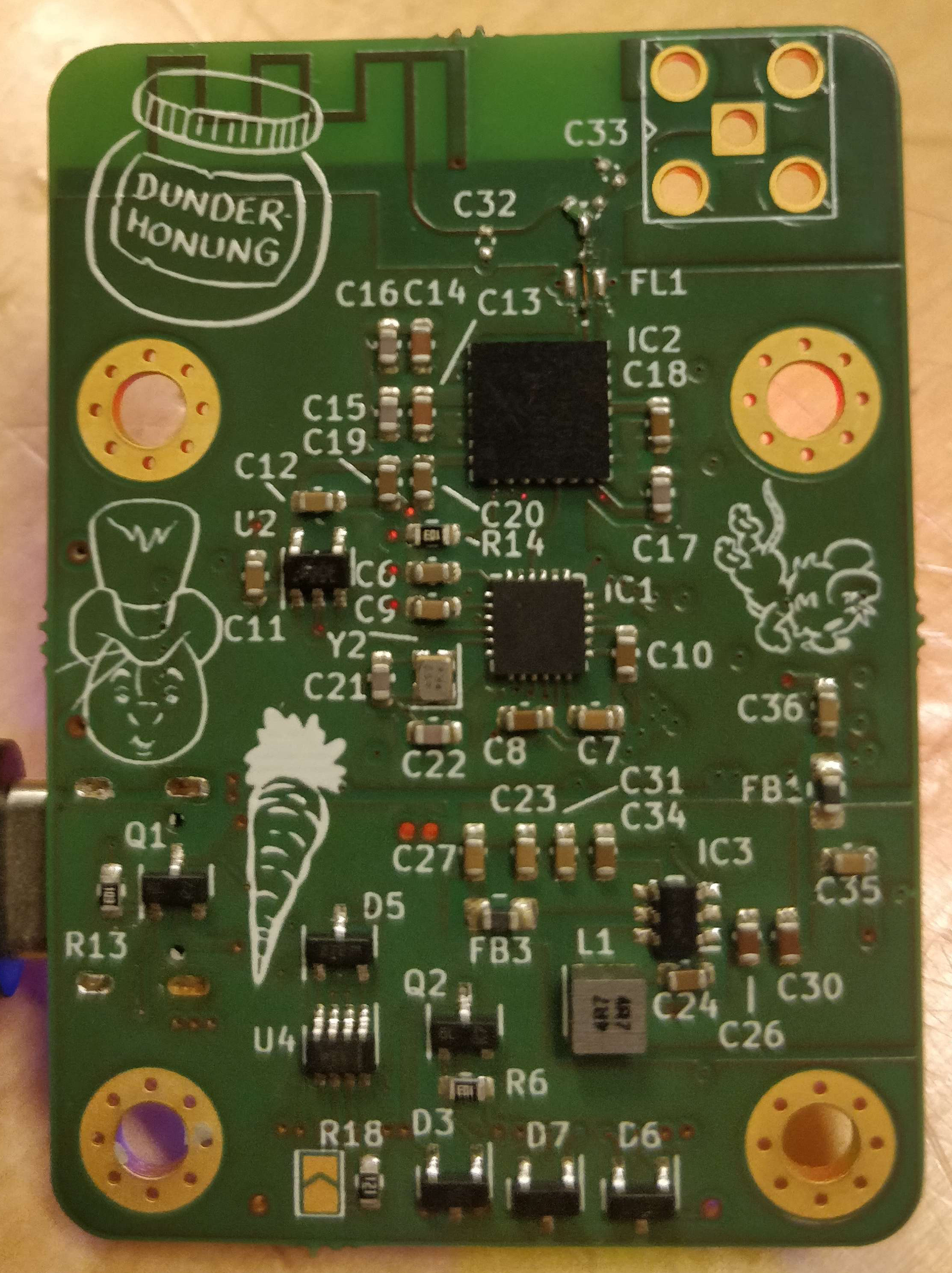 |
The modem is based on an STM32U575CG and an SX1280 transceiver. The radio signal is put through a frontend, filtering and amplifying it to 30dBm. The UART and CAN connectors follow the PixHawk standard while the debugging port is custom.
The firmware is being developed using Rust with Embassy. See the firmware README
| Qty | Value | Footprint | References |
|---|---|---|---|
| 9 | 100n | Capacitor_SMD:C_0603_1608Metric | C8, C10, C18, C19, C20, C24, C25, C29, C34 |
| 8 | 1u | Capacitor_SMD:C_0603_1608Metric | C7, C11, C12, C23, C27, C31, C35, C36 |
| 7 | 18p | Capacitor_SMD:C_0603_1608Metric | C3, C5, C15, C16, C17, C21, C22 |
| 6 | 10k | Resistor_SMD:R_0603_1608Metric | R1, R2, R3, R6, R13, R14 |
| 6 | LOGO | LOGO | G***, G***, G***, G***, G***, G*** |
| 5 | 1M | Resistor_SMD:R_0603_1608Metric | R5, R8, R15, R16, R17 |
| 5 | 330 | Resistor_SMD:R_0603_1608Metric | R11, R12, R19, R20, R21 |
| 5 | 4u7 | Capacitor_SMD:C_0603_1608Metric | C1, C2, C4, C13, C14 |
| 4 | MountingHole_Pad | MountingHole:MountingHole_3.2mm_M3_Pad_Via | H1, H2, H3, H4 |
| 4 | SZNUP2105L | Package_TO_SOT_SMD:SOT-23 | D3, D5, D6, D7 |
| 2 | 0 | Resistor_SMD:R_0402_1005Metric | R4, R7 |
| 2 | 10n | Capacitor_SMD:C_0603_1608Metric | C6, C9 |
| 2 | 10u | Capacitor_SMD:C_0603_1608Metric | C26, C30 |
| 2 | 5k1 | Resistor_SMD:R_0603_1608Metric | R9, R10 |
| 2 | BLM18KG102SN1D | Inductor_SMD:L_0805_2012Metric_Pad1.15x1.40mm_HandSolder | FB1, FB3 |
| 2 | DMP3056L-7 | Package_TO_SOT_SMD:SOT-23 | Q1, Q2 |
| 2 | TBD | Capacitor_SMD:C_0402_1005Metric | C32, C33 |
| 1 | 120 | Resistor_SMD:R_0603_1608Metric | R18 |
| 1 | 4.7u | Inductor_SMD_Wurth:L_Wurth_WE-LQSH-3012 | L1 |
| 1 | 48MHz | Crystal:Crystal_SMD_2016-4Pin_2.0x1.6mm | Y1 |
| 1 | 52MHz | Crystal:Crystal_SMD_2016-4Pin_2.0x1.6mm | Y2 |
| 1 | Conn_Coaxial | Connector_Coaxial:SMA_Amphenol_901-143_Horizontal | J2 |
| 1 | DEA202450BT-1213C1 | dea202450bt1261:DEA202450BT1261A2 | FL1 |
| 1 | IN-S128TATRGB | LED_SMD:LED_RGB_1210 | D9 |
| 1 | LMR50410Y3 | lmr50410:SOT95P280X145-6N | IC3 |
| 1 | NTCG203NH103JT1 | Resistor_SMD:R_0805_2012Metric_Pad1.20x1.40mm_HandSolder | TH1 |
| 1 | SKY65383-11 | sky65383:SKY6538311 | IC2 |
| 1 | STM32U575CGTx | Package_QFP:LQFP-48_7x7mm_P0.5mm | U1 |
| 1 | SX1281IMLTRT | sx1281:QFN50P400X400X100-25N-D | IC1 |
| 1 | SolderJumper_2_Open | Jumper:SolderJumper-2_P1.3mm_Open_TrianglePad1.0x1.5mm | JP1 |
| 1 | TCAN334GDCN | Package_TO_SOT_SMD:TSOT-23-8 | U4 |
| 1 | TPS7A20285PDBVR | Package_TO_SOT_SMD:SOT-23-5 | U2 |
| 1 | USBLC6-2SC6 | Package_TO_SOT_SMD:SOT-23-6 | U3 |
| 1 | USB_C_Receptacle_USB2.0 | Connector_USB:USB_C_Receptacle_Palconn_UTC16-G | J3 |
| 1 | inverted F | RF_Antenna:Texas_SWRA117D_2.4GHz_Left | AE1 |
| 1 | jst gh 4 | Connector_JST:JST_GH_SM04B-GHS-TB_1x04-1MP_P1.25mm_Horizontal | J4 |
| 1 | jst gh 6 | Connector_JST:JST_GH_SM06B-GHS-TB_1x06-1MP_P1.25mm_Horizontal | J5 |
| 1 | jst_sh 6 | Connector_JST:JST_SH_SM06B-SRSS-TB_1x06-1MP_P1.00mm_Horizontal | J1 |
| 1 | rx | LED_SMD:LED_0805_2012Metric | D2 |
| 1 | tx | LED_SMD:LED_0805_2012Metric | D1 |
It measures 38 × 53 mm and has 4 copper layers, 1.6 mm thick.
96 parts, built around the SKY65383-11, SX1281IMLTRT, TCAN334GDCN and DEA202450BT-1213C1. The full list of its parts is on this page, with links to each part's symbol and footprint where PCBKit's library has them.
From the klownfish/brage_telemetry repository on GitHub, at the commit this page was made from: the board is hardware/1280_modem.kicad_pcb and its schematic hardware/1280_modem.kicad_sch. PCBKit opens the board in the browser, with nothing to install.
Its repository states no licence, so its author keeps all rights: ask klownfish before reusing the design.
LorenzoCucchi/ELRS-SX1281
2.4 GHz LoRa board featuring the SX1281 and the SKY65383-11 frontend


jbrown3859/EE175-SeniorDesign
CubeSat Flight Computer and Radio - EE175 Senior Design F22


nobodywasishere/ee193
This is a breakout board for the ST STTS75M2F and TDK NTCG103JF103FT1 design with KiCAD 6. PCB image generated using PcbDraw.

dognotdog/smol_servo
circuitry and software for controlling NEMA17 size brushless motors and stepper motors as servos.