Skip to the content
PCBKitNew board
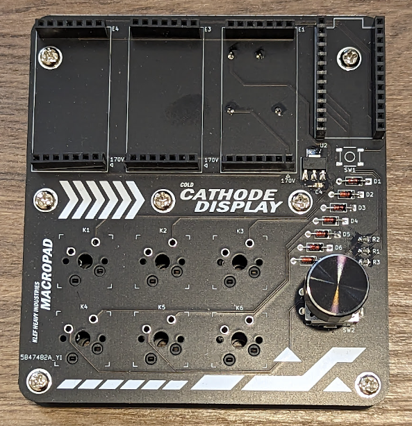
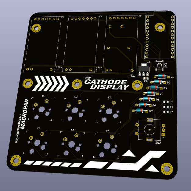
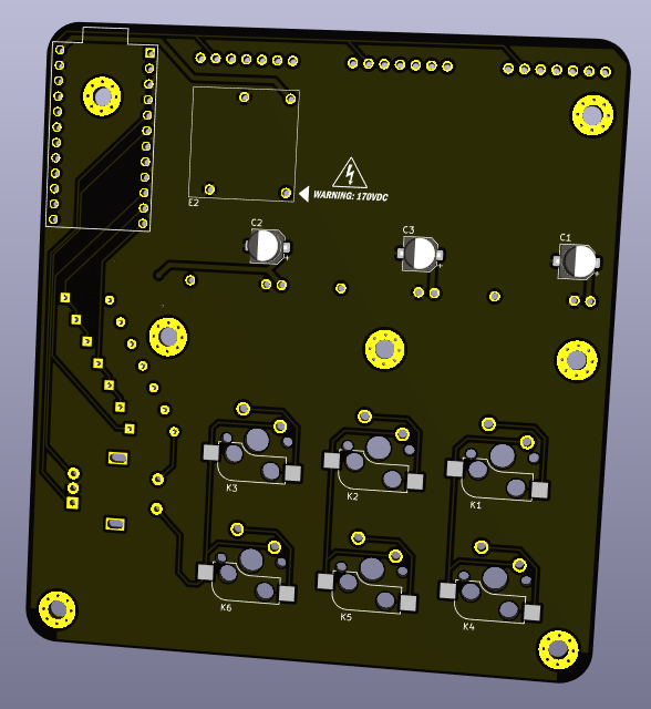
2 layers95.1 × 104 mmPhi, the printed circuit board in 3D

6 button + rotary dial 3 digit nixie tube macropad

Size
95.1 × 104 mm
Copper layers
2
Thickness
1.6 mm
Parts
37
Nets
46
Pads
218
Tracks, vias
263, 3
Pours
1
Routed
Yes
KiCad
KiCad 7 (file 20221018)
Created
16 Jun 2026
Updated
16 Jun 2026

Overview

Phi is an open-source printed circuit board by klefff, from the klefff/nixie-macropad repository on GitHub, published under the MIT licence. It is a 2-layer board of 95.1 × 104 mm with 37 parts on 46 nets, routed with 263 tracks and 3 vias.

Its parts include 8 switches, 7 diodes, 4 capacitors, 3 resistors and 2 ICs. It belongs with the keyboards and input and lEDs and displays boards and the AVR (ATmega, ATtiny) boards of this library.
README

README.md

nixie-macropad

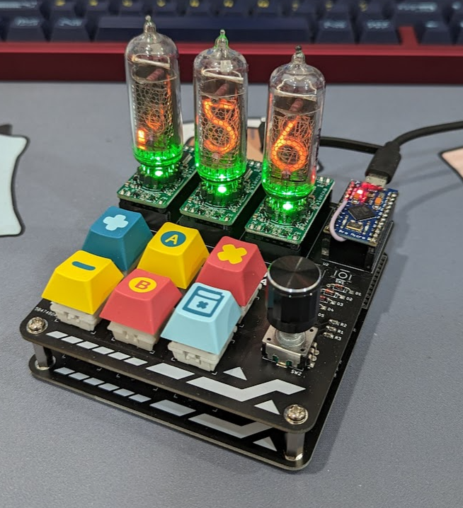
Simple 2x3 macropad with encoder that has a 3 digit nixie tube display that can be programmed for various functions over QMK.

Usage:

Feel free to try replicate with care, as this is an unpolished proof of concept that I will probably build on later. Enjoy!
Hardware Notes:

  • Not sure but it seems the boards that I am using to drive the Nixie tubes might be discontinued. However the developer open-sourced them, so you might be able to make them yourself. (Planning to make my own for future builds)

Main Features:

  • 3x IN-14 Nixie Tubes with numbers 0-9 plus left comma
  • Uses QMK
  • Display current volume of connected Windows device via RAWHID
  • EC11 Encoder + button
  • 2x3 Macropad with Kailh Hotswap
  • Only USB connected to PC needed

Software Installation:

Windows Node Script:

  1. Download the 'Node Script' folder
  2. Follow the steps in 'Development Setup' and/or 'Using the Script' from BlankSourceCode's repo

QMK:

  1. You need to flash the Pro Micro with custom QMK firmware
  2. Build for Phi (Default)

Hardware:

Before Assembling:

  1. For the Exixes, you need to attach the Nixie tubes to the boards.
    • I just soldered machine sockets to the boards and shoved the Nixie tube pins into the sockets (gingerly)
    • Or follow their recommended method

Assembly

  1. Make the custom PCBs (needs 2, or make a case)
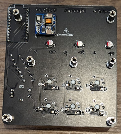
  2. Solder on the required components below (see pictures)
  3. Assemble such that two of the custom PCBs make a basic case thing
  4. Choose some cool keycaps and knob

Bill of Materials:

  • 2x Custom PCBS
    • Sandwich with 7x 15mm standoffs (M3 Size)
  • 3x Exixe
    • Nixie tube driver modules with SPI communication
  • 3x IN-14 Nixie Tubes with 0-9 digit and left comma (at least)
  • 1x Pro Micro or similar pinout with QMK support
  • 2x Custom base PCB that doubles as stand
    • See PCB build files
  • 6x Kailh Hotswap switch sockets
  • 1x 2.5-15VDC to 170VDC DC-DC convertor or similar
  • 1x Any type of EC11 rotary encoder
  • 1x SMD 3.3V Voltage Regulator
    • Needed to power the Exixes
  • 3x 10uF Electrolytic Capacitors
    • Required for the Voltage Reg
  • 1x 0.1uF Ceramic Capacitor
  • 7x Diodes
  • 3x 470 Ohm SMD Resistors
  • Some 2.54mm pitch connectors (if you don't want to direct solder)
    • I like machine sockets but normal 'Arduino'-esque ones are good too
    • 3x 7 pin for Exixe comms
    • 2x 12 pin for Pro Micro
    • 7x 1 pin (if you can find them or just cut bigger ones)
      • For 170V DC-DC convertor and Exixe 170V
    • 2x 2 pin for Exixe 3V
    • For the above 2, you can also just get 7 pin ones and take out the middle 4 pins
  • Some keycaps
  • An encoder knob

Additional:

Housekeeping:

  • Every ~15 mins the tubes will cycle all digits to reduce change of cathode poisoning

Future Work:

  • Possible adding VIA capabilities for flashing
  • Adding more uses for the 3 tube digits; current weather, CPU usage etc
  • Adding another digit for RTC time
  • Bluetooth/Wireless with battery

References:

Parts

37
QtyValueFootprintReferences
71N4148Diode_THT:D_DO-35_SOD27_P7.62mm_HorizontalD1, D2, D3, D4, D5, D6, D7
6KEYSWkeyswitches:Kailh_socket_MX_optionalK1, K2, K3, K4, K5, K6
310uf ELCapacitor_SMD:CP_Elec_5x5.8C1, C2, C3
3470RResistor_SMD:R_0805_2012Metric_Pad1.20x1.40mm_HandSolderR1, R2, R3
3~exixe:exixe14E1, E3, E4
2LOGOLOGOG***, G***
10.1uF CCapacitor_SMD:C_0805_2012Metric_Pad1.18x1.45mm_HandSolderC4
1LD1117S33TR_SOT223Package_TO_SOT_SMD:SOT-223-3_TabPin2U2
1ProMicropromicro:ProMicroU1
1RotaryEncoder_SwitchRotary_Encoder:RotaryEncoder_Alps_EC11E-Switch_Vertical_H20mmSW2
1SW_Push_DualSwitches:TACTILE_SWITCH_SMD_5.2MMSW1
1~nch8200hv:NCH8200HVE2

The 30 most common of 37 parts.

Questions

How big is the Phi PCB?

It measures 95.1 × 104 mm and has 2 copper layers, 1.6 mm thick.

What parts does the Phi use?

37 parts. The full list of its parts is on this page, with links to each part's symbol and footprint where PCBKit's library has them.

Where can I download the Phi KiCad files?

From the klefff/nixie-macropad repository on GitHub, at the commit this page was made from: the board is PCB/phi.kicad_pcb and its schematic PCB/phi.kicad_sch. PCBKit opens the board in the browser, with nothing to install.

Can I use the Phi design in my own project?

Its repository publishes it under the MIT licence: you may reuse it on that licence's terms (keep the author's notice, and for a copyleft licence share your changes alike).

Similar boards

  • 2 layers40 × 34 mmDD HIP9011, the printed circuit board in 3D

    DD HIP9011

    rusefi/rusefi

    rusefi - GPL internal combustion engine control unit

    37 parts1.2k
  • 2 layers53.9 × 23.2 mmAnalog, the printed circuit board in 3D

    Analog

    hoglet67/RGBtoHDMI

    Bare-metal Raspberry Pi project that provides pixel-perfect sampling of Retro Computer RGB/YUV video and conversion to HDMI

    37 parts1kGPL-3.0
  • 2 layers52 × 51.8 mmEsp32-homeassistant rf bridge, the printed circuit board in 3D

    Esp32-homeassistant rf bridge

    hackclub/OnBoard

    💡 Join 1,000 teenagers and make your first PCB with a $100 grant!

    37 parts915
  • 2 layers87.8 × 59.8 mmFreeDeck SMD 2020-02, the printed circuit board in 3D

    FreeDeck SMD 2020-02

    FreeYourStream/freedeck-hardware

    all the stuff you need to build your own FreeDeck

    37 parts772
  • 2 layers65 × 28 mmBMS Cell Module, the printed circuit board in 3D

    BMS Cell Module

    stuartpittaway/diyBMS

    Do it yourself battery management system for Lithium ion battery packs/cells

    37 parts676GPL-3.0
  • 2 layers48 × 32 mmFlatSat, the printed circuit board in 3D

    FlatSat

    Pwnsat/FlatSat

    Flatsat v1.0 is a hardware based platform for aerospace cybersecurity research

    37 parts575GPL-2.0
  • 2 layers38.1 × 153.7 mmDEFOG PANEL, the printed circuit board in 3D

    DEFOG PANEL

    jrsteensen/OpenHornet

    OpenHornet 1:1 F/A-18C Simulator Repository

    37 parts431
  • 2 layers47.8 × 27.4 mmVsf stm32h7b0, the printed circuit board in 3D

    Vsf stm32h7b0

    vsfteam/vsf

    Versaloon Software Framework -- a tiny preemptive-capable event-driven incremental software framework for embedded systems

    37 parts341Apache-2.0